This thread has been locked.

If you have a related question, please click the "Ask a related question" button in the top right corner. The newly created question will be automatically linked to this question.

AFE7225EVM: Test without TSW1400EVM and/or RX-TX Loopback

Part Number: AFE7225EVM
Other Parts Discussed in Thread: AFE7222, , CDCE72010, AFE7225

Hi,

I have AFE7225EVM which has AFE7222 analog front end IC on it. I want to test the board without using TSW140x EVM's. I know that the easiest way is to use TSW boards but I need to be sure that my AFE board is working before purchasing th TSW board. I read the datasheet and there is an option to use RX-TX loopback. I have tried to change most of the registers that may be related with loopback but could not manage it.

Here is my test configuration:

The board is powered by 6V Wall Adapter supplied by TI, power jumpers are left as-is and checked that they are correct according to AFE7225EVM User Guide.

1. CDC Aux IN: 24MHz Sine Wave (2Vpp)

2. INA or INB: 1MHz or 2Mhz or 4MHz Sine Wave - 1MHz or 2Mhz or 4MHz Carrier AM/FM Modulated signal (2Vpp and max. 20kHz bandwidth) - Tried all combinations with nearly all settings.

3. IOUTA or IOUTB are connected to Spectrum Analyzer.

4. CDC registers are remain the same, AFE is clocked /3 of Aux (8Mhz), tried to divide it by /1, still no luck.

5. Tried AFE7225_reg.txt and CDCE72010_reg.txt that is supplied with GUI. Just set RX_TX_LBPK and RX_TX_LBPK_SRC at the same time.

6. Tried to reset all the registers and just set RX_TX_LBPK and RX_TX_LBPK_SRC at the same time.

7. Tried to enable CMIX, MIXERs, QMC options on both RX and TX channels.

8. Tried to enable FIFO options on TX channels.

9. Tried to connect Input to A and B channels and forwarded all DACs to same channels.

And also tried another options but still no luck. Could you please explain me that if it is possible to use loopback function in such way or did I misunderstand the whole concept? Or is there anyway to test the AFE7225EVM without TSW boards?

Thanks for your time,

Regards,

Yasin

  • Hi Yasin,

    We are looking at your question and will get back to you soon.

    Regards,
    Neeraj
  • Hey Yasin,

    I have never tried to run the board in loopback mode. What exactly is the problem? Obviously you cannot get loopback mode to work. But can you verify a few things before me move forward.

    Can you verify that all of the IC's are power correctly and using an oscope, can you verify that that the clocks are present at the correct pins. Are you positive the GUI is communicating the EVM? Maybe probe the SPI pins while programming the GUI to confirm. While you're double checking your hardware, I will try and get in the lab today to get this up and running.

    Yusuf
  • Hi Yusuf,

    First, thanks for your quick reply.

    I don't know what is the exact problem but I want to make sure that I am not missing any step to put the card in a loopback mode. So I tried to describe my setup in detail. According to the datasheet, if SPI is working and the clocks and voltages are present, only setting the RX-TX-LBPK and RX-TX-LBPK-SRC bits are enough. AFAIK, my clocking scheme (24MHz on CDC AUX with /3 division, max. 4MHz input signal on INA or INB that is sine or 20kHz AM/FM modulated) seems to be correct at least to have some output on IOUTA or IOUTB that can be analayzed on Spectrum Analyzer.

    I have checked the voltages on the ICs and TPs, Vcm voltage is about 1.78V but did not check the clocks. I am gonna let you know once I have double checked the voltages, clocks and probed the SPI.

    Hope you can make the loopback mode running in the lab and I would be appreciated if you let me know about the lab test results.

    Regards,

    Yasin

  • Hi Yusuf,

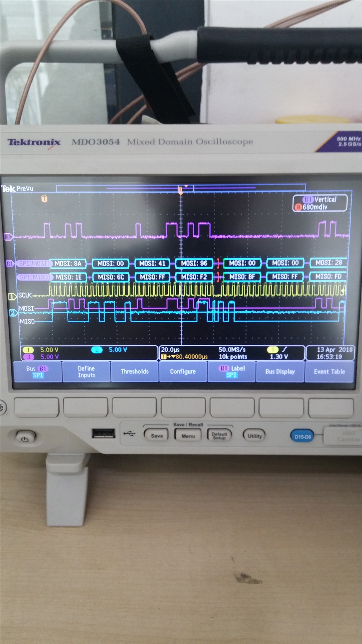
    I have double checked all the voltages on the card, both on test points and on the IC pins seem to be correct. I have probed SPI and seems to be working. Attached you can find "Send All" SPI command of CDC, for AFE I have observed the SPI clock and SPI data is available but have no picture since the connections are not routed to pins for easy measurement.

    I realized that C83 (10nF capacitor) that is connected from CDC AUX IN SMA connector to CDC IC is missing on my board. So CDC seems not to be clocked by AUX IN. I double checked the schematic (that is belong to REV.C but my EVm is Rev.B) and C83 is not labelled as DNI. Also in my card's configuration, components in front of CLKIN SMA connector is not fitted. What is your alternative clocking scheme for my board? Can I short the pins of C83? Or without CDC IC, how can I clock the EVM and test the loopback function?

    Please let me know if you need further clarification.

    Regards,

    Yasin

  • Yasin,

    I think the AFE7225 comes with an on-board 19.2MHz crystal routed to the secondary reference input for CDC. With the right dividers you can use this option to generate clocks for the rest of the EVM. You can also provide the clocks externally to the AFE and FPGA as they are options seenin the schematic. Just make sure your clock sources are in phase with one another.

    Yusuf

  • Hey Yusuf,

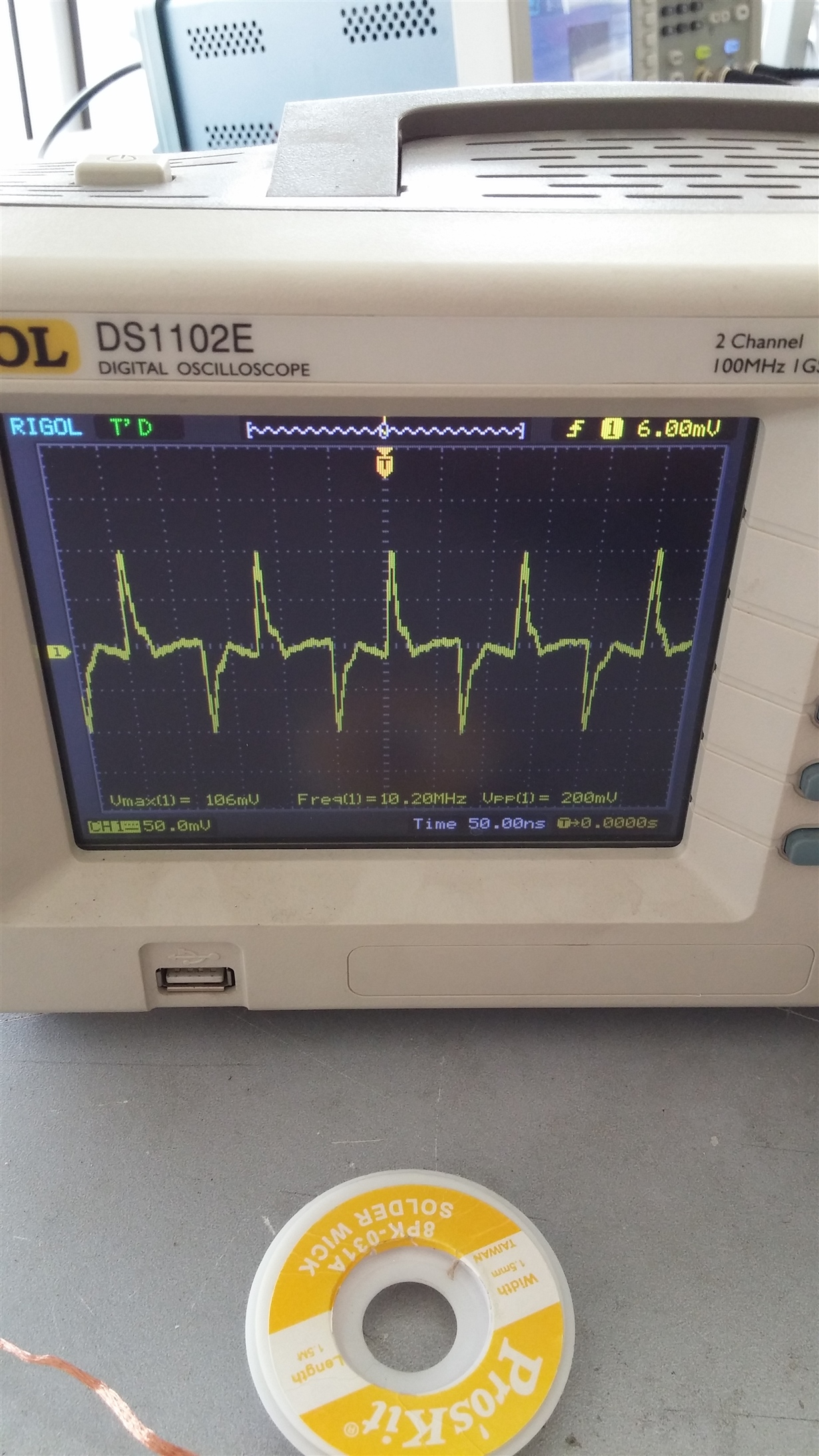
    I have installed the C83 (10nF 10V 201package capacitor) and the CDC IC is clocked succesfully. However, AFE seems not to be clocked. I have clocked the CDC AUX with 24MHz sine, set the divider of Output 0 to /3 nd the measured output is below:

    Meas. 1 - Clock Measurment of Output 0 of the CDC - div /3 (Default input of the T9 RF Transformator):

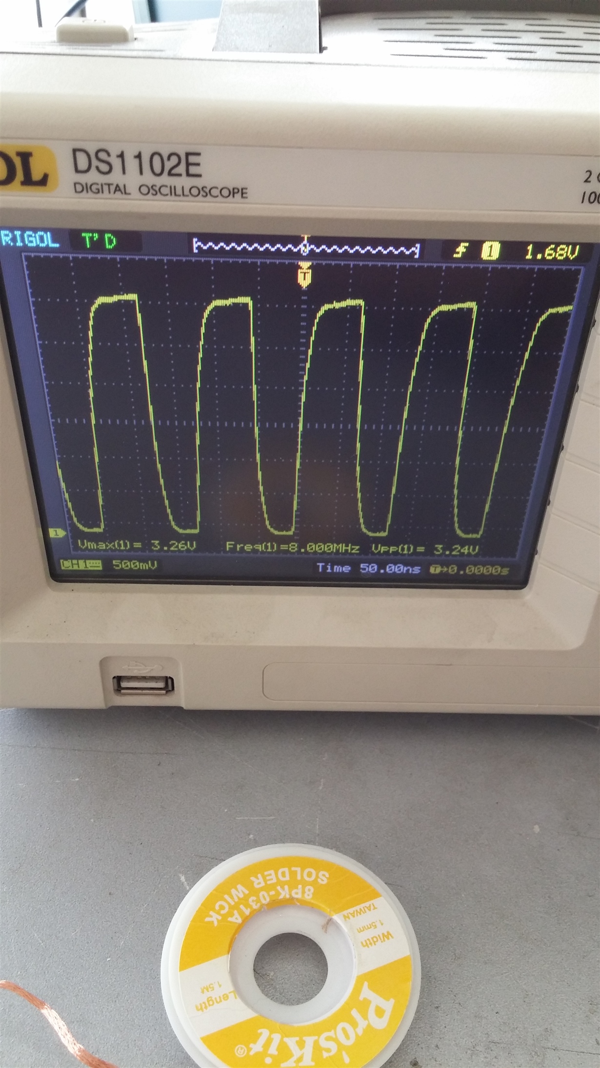
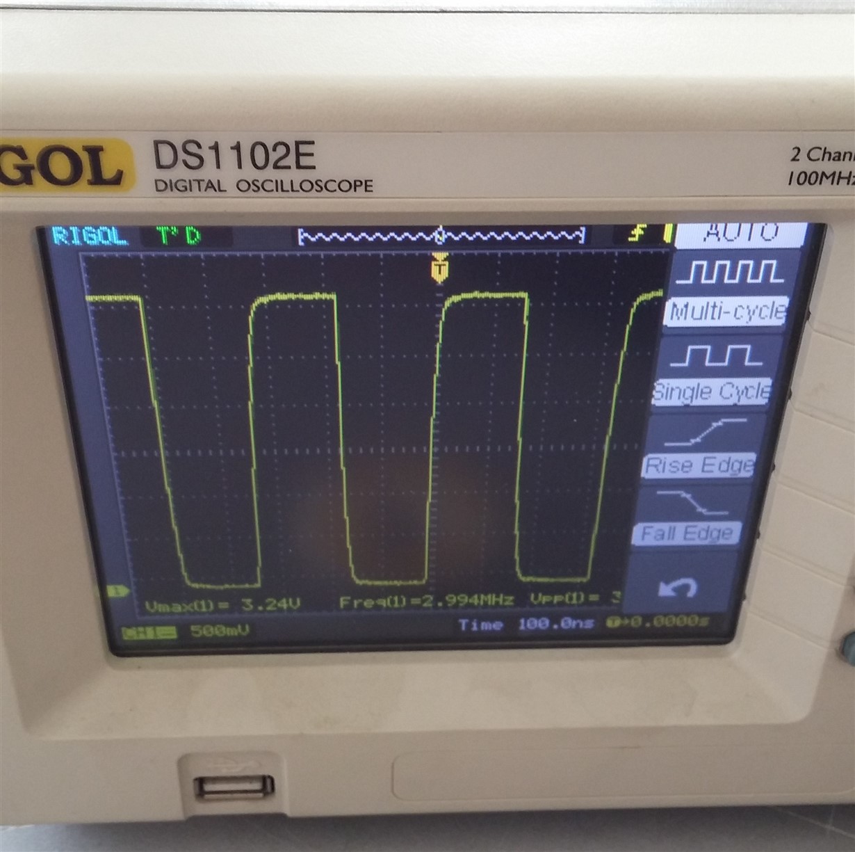
    I also measured the Output 1 and Output 8 of the CDC and they seemed to be correct and results are shown below:

    Meas. 2 - Clock Measurment of Output 1 of the CDC - div /3


    Meas. 3 - Clock Measurment of Output 8 of the CDC - div /8

    So I tried to select the Output 1 as the AFE clock source, I removed R76 and installed R79 0R resistor. But this time Output 0 of the CDC has normal clock signal like Meas. 2 and Output 1 is like Meas. 1.

    I don't know what is causing that kind of problem but AFE seems not to be clocked as RF transformator has no output since input is not valid.

    Please let me know if you have any troubleshooting steps for this problem and if you need further information.

    Regards,

    Yasin

  • Hey Yasin, 

    I am still trying to get my hands on a functional AFE7225 sorry for the delay. Its interesting that whatever is connected to the transformer seems to distort. Just to verify this, remove R74, R76 AND R79 and probe the resistor pads closest to the CDC. If both signals are clean from the CDC then  there may be something up with the transformer.

    You can also install R74 and provide a clock externally using a sig gen. Do you still see the signal distorted at the input of the transformer and no output from the transformer? This too would further verify that maybe the transformer is distorting your signal somehow. Make sure R86 is installed to make sure the other input to T9 is grounded. I am still looking for a board so hopefully i can get one up and running to be of better help.  

    Yusuf