This thread has been locked.

If you have a related question, please click the "Ask a related question" button in the top right corner. The newly created question will be automatically linked to this question.

DRV8811 design resets sporadically

Other Parts Discussed in Thread: DRV8811, DRV8818, AM3359

Greetings!

I have a DRV8811 based design which resets sporadically, but only when the motor is running.  Other than that, I can't seem to correlate the reset event with any other activity.

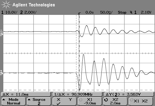
The design point for motor current is about 600ma. Vm is 24v.  It is set for mixed decay. The motor is being full stepped.  I put a scope and ground on one of the H-Bridge .33 ohm sense resistors. When the reset occurs, I see a negative voltage spike at the sense point which seems to equate to a -10A transient, of about 10 to 20 ns.  With a 100MHz scope, that is the limit of my resolution. This current spike appears to be followed within ns by a noise spike on my 5V supply, the 3.3v supply, and the reset line.

The spike can happen anywhere in the motor step/pwm cycle.
I am looking for any advice in how to rule my DRV8811 implementation in or out as a culprit.

Gerry Belanger

  • Hi Gerry,

    There are a few things to look at. Please monitor the HOMEn signal and the current when running.

    Are you seeing a HOMEn signal assert at the proper times? For example in full step, HOMEn should assert every 4th step.

    If not, this is an indication of a fault occuring and the DRV8811 is resetting back to HOME. The fault can be an overtemp or an overcurrent, or it could be an undervoltage event.

    Also noise on signals like RESETn and SLEEPn can cause the HOMEn to reset. If you suspect SLEEPn, the charge pump will be disabled so look for a droop on VCP.

    Another signal is the ENABLEn. If it is subject to noise, HOMEn should not be affected.

    Any scope captures you can provide will make debug easier.  Thanks.

    Also

  • Rick Duncan said:

    There are a few things to look at. Please monitor the HOMEn signal and the current when running.

    Are you seeing a HOMEn signal assert at the proper times? For example in full step, HOMEn should assert every 4th step.

    If not, this is an indication of a fault occuring and the DRV8811 is resetting back to HOME. The fault can be an overtemp or an overcurrent, or it could be an undervoltage event.

    Rick,
    HOMEn appears to be behaving as expected.  It goes active every 4th step.  If the reset event occurs when HOMEn is inactive, it goes active after the processor reset brings RESETn active.

    Also noise on signals like RESETn and SLEEPn can cause the HOMEn to reset. If you suspect SLEEPn, the charge pump will be disabled so look for a droop on VCP.

    SLEEPn is unused and tied off to 3.3v VCC through a 10 k resistor.

    Another signal is the ENABLEn. If it is subject to noise, HOMEn should not be affected.

    I have seen no noise on ENABLEn until the spike hits.

    Any scope captures you can provide will make debug easier.  Thanks.

    Here is a scope shot of the sense resistor (bottom) and cpu reset (top) when the reset event hits

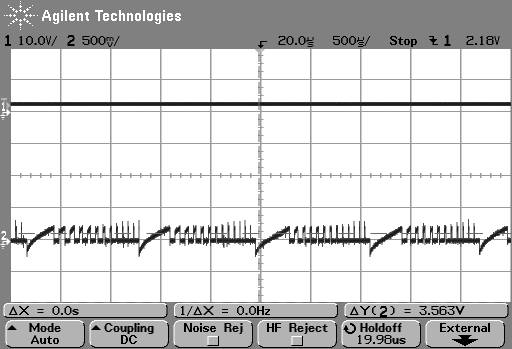
    And here is the sense resistor (0.33 ohms) during normal operation.

    Would there be anything to be gained by dropping a DRV8818 into the slot?

    Gerry Belanger

  • The scope shots did not come through.  Let's try it again.

    Scope shot of cpu reset (top) and current spike i a sense resistor.

    And one of normal operation

    Hopefully that one worked.

    GerryB

  • Hi Gerry,

    A few more questions. I know you have two DRV8811s on your board.

    Can you run one at a time and determine which site is causing the problem? When you are running do you stop the motor at any point? What are your motor parameters?

    Using a DRV8818 may help if the problem is overtemp, but it probably will not help for anything else.

  • Rick,

    The system design is such that the motors cannot run at the same time.  Thus, to save I/O pins, some lines are shared .  See http://e2e.ti.com/support/applications/motor_drivers/f/38/p/208166/810754.aspx#810754.

    It is Motor A , U10 in my schematic, which is running when I see the resets. 

    The motor runs only when an operation is required, a few seconds at a time. The motor does stop once to reverse direction  When it is done, it is stopped.  Then motor B runs a cycle of less than 500MS.  then all go idle until the next operation is required.

    The resets I have seen happen during running, which is the longest time.  It never happens when the motor is not running.

    The motor is a PM stepper, 24V, 3.7 ohms/phase, 600ma/phase..

    GerryB

  • Hi Gerry,

    Do you have a current probe to capture the current through motor A when the event occurs? The spike on the sense resistor is implying 12A. Hopefully these current spikes will help us narrow down the suspected area.

    I understand you had a couple of comments on the board review.

    For comment 1, please inform the customer know that 600mA is the desired chopping current. During the blanking time of 1.4us the current could be larger.

    Comment 3 is probably a misinterpretation of the layout. The path from pin 15 to C39 is fine. The path from C39 ground back to pin 21 was what I had trouble following. Since it is a ground plane with no cuts, it is fine.

  • Rick,

    We do have a current probe, but it is only rated for 100KHz, so I would not expect it to be of nay use catching a 20ns spike. 


    I assume the wide ramps in the running scope shot  would be a step command, the blanking interval, and current ramp up to the first PWM cycle of a step.  I see no excess current there. 

    I cannot correlate the spike with any particular point in a step cycle.  I would like to rule out the DRV8811 as a culprit, but he spike just before reset still needs to be explained.

    Gerryb

  • Hi Gerry,

    Can you describe the debug steps that got you to the reset voltage spike? Sometimes I find myself focusing on the effect and miss the cause.

    Please examine each of the remaining 3 sense resistors. It is possible that one on the windings has lost current regulation. If this happens, the overcurrent will assert.

    When U10 is running, is U8 enabled and holding? How often does the reset spike occur when U10 is running?

    Thanks.

  • Rick,

    With the printer resetting sporadically during normal operation, I looked at the reset line with the scope to see what was going on.  Then I looked at various other signals to try to determine what was happening to cause the spike.  the current spike was the only signal I found where the noise spike preceded the reset spike.  During operation, the spike can occur at any time when the primary motor is running.  The spikes seem more frequent when the system starts up from cold.  Eventually, we

    If a winding loses current regulation, then I may have an intermittent motor, as it runs properly most of the time.  Possible.  I will get it swapped out. 

    When U10 is running, U8 is off, with its enable low.

    GerryB

  • Hi Gerry,

    <When U10 is running, U8 is off, with its enable low>

    Just to clarify, is U8 enable low or high when U10 is running? The ENABLEn is active low, so U8 would remain active. 

    Thanks.

  • Hi Gerry,

    There was a typo on the previous post. I meant to say U8 would remain active. I have corrected the post.

  • Rick,

    I was speaking with my software hat on.  I have an inverting driver in the enable line, so from the software side, low is off.

    Here is a scope shot of a complete U8 cycle, ENABLEn and STEP at the chip.

    8551.U8.TIF


    It shows acceleration, stop for reversing, then acceleration to stop.  This motor is half stepping.

    GerryB

  • Hi Gerry,

    No worries. I forget which hat I have on also. Just want to confirm.

    Have you looked at the other sense resistor of U10? Also let's try to rule out all possible causes of resetting the DRV8811.

    Not in any particular order:

    1) Overtemp -- Can you set the CN_MOT_VREF signal to a logic one to reduce the current when running? Does the problem go away when using lower current?
    2) UVLO -- VM (unlikely). Please monitor VM with respect to local GND near the device. Is it dropping below 8V?
    3) UVLO -- VCC (unlikely also). Please monitor VCC with respect to GND near the device. Is it dropping below 2.95V?
    4) Overcurrent -- Do you currents in either winding exceeding 2.5A. This is not chopping current.

  • Rick,

    The other U10 sense resistor showed some current transient at reset time, but was not as severe as the side I scoped.

    1) Overtemp: setting lower power did nothing to prevent the reset.  I had intended that in case I needed to actively hold position.

    2) ULVO - VM never drops below 20V

    3) ULVO: The 3.3V experiences a spike, coincident with the spike on reset, which, to my scope, appears slightly after the current spike.

    4)  The motor windings, with the current probe, look to be about 600ma, reversing with each (full) step.

    Here is a shot, reset on CH1, a motor winding via a 100mv/A current probe on CH2.

    2234.20-MotorCurrent_at_reset.TIF


  • Hi Gerry,

    Can you provide the date code on the device in question? Typically, there are three lines printed on the top of the device. If you provide all three lines or a picture of the top of the device that will do.

    Thanks.

  • DRV8811

          25TC

          ACY9

    GerryB

  • Hi Gerry,

    Thanks. I sure you are curious. Someone had asked if you are using the latest version of the device. You are.

  • Rick,

    In order to try to isolate the problem further, we lifted the Vcc pin and hotwired in a separate supply from a LM2594M-5.0 pitch pack.  This allowed me to put a current probe in the Icc feed.  During normal operation the DRV8811 appears to be drawing less than the 4mA listed as Ivcc max.  When my reset event happens, the Ivcc spikes to 440mA.  With rise and fall times, it looks like a 40ns current spike.  That could cause the chip to do this?

    Gerry Belanger

  • I meant:  What could cause the chip to do this?

    Gerard Belanger1 said:

    Rick,

    In order to try to isolate the problem further, we lifted the Vcc pin and hotwired in a separate supply from a LM2594M-5.0 pitch pack.  This allowed me to put a current probe in the Icc feed.  During normal operation the DRV8811 appears to be drawing less than the 4mA listed as Ivcc max.  When my reset event happens, the Ivcc spikes to 440mA.  With rise and fall times, it looks like a 40ns current spike.  That could cause the chip to do this?

    Gerry Belanger

  • Hi Gerry,

    I will check and get back to you.

  • Hi Gerry,

    When the event occurs, it looks like several pins are going negative. ISENA is going to -4V, and RESET is going to -3V. Both of these excursions violated the absolute minimums of the device and can cause parasistic circuitry to activate.

    Our design team has requested that you capture the AOUT1 and AOUT2 pins along with the ISENSA (zoomed in as before).

    I forgot to ask if you are running paper through the device when this event occurs. If so, could an ESD event cause this to happen?

    You mentioned swapping motors. Did you do that?
    Have you tried a second board?
    It may also be time to swap to the DRV8818 for another datapoint. If you don't have one, samples can be ordered.

  • Rick,

    Yes we are running paper.  Static was an early concern.  Between the stainless steel, and the static brushes, we do not believe that to be a problem.  We have tried 3 boards, and 3 motors.  No difference.  The huge negative on the reset line may or may not be real, as everything goes bonkers when the transient hits.

    I did notice yesterday that the step signal goes go to -800mV.  That is the only motor driver control signal which changes during operation.  I could not correlate the reset event with any particular point in the step cycle. 

    The step signal is generated from a Timer on a TI AM3359.  I had configured the I/O cell as fast slew rate.  I changed it to slow, with no effect.  I found a post from a TI engineer in the Sitara forum which said that there was no appreciable difference between fast and slow, so TI does not characterize slow at all. 
    I left instructions for my tech to try a series termination to reduce that transient in case it was causing upset on the chip.  I am currently on vacation, but hope to hear from him via e-mail.

    We did buy some DRV8818 parts, as sampling through distribution was not working.

    GerryB

  • More information.

    I now have a correlation I can duplicate.  Humidity, or lack thereof. For a month, we experienced no resets while the weather was humid.  A couple of dry weekends resulted in a few Monday morning resets.  So we set up a dehumidifier in a small room to get the RH down to 40% and voila, consistent resets on start-up on one unit.  A second, allegedly identical unit,  does not experience resets.

    Even in the dry room, once we get past the start-up resets, the unit works fine.

    This makes me wonder what kind of failure mechanism the DRV8811 might experience if the CEM did not take moisture precautions prior to mounting the chip on the board.

    Gerry Belanger.

  • Hi Gerry,

    Thanks for providing this information. Please keep us informed on any future developments.