This thread has been locked.

If you have a related question, please click the "Ask a related question" button in the top right corner. The newly created question will be automatically linked to this question.

DRV8308 EVM - speed control

Other Parts Discussed in Thread: DRV8308EVM, DRV8308

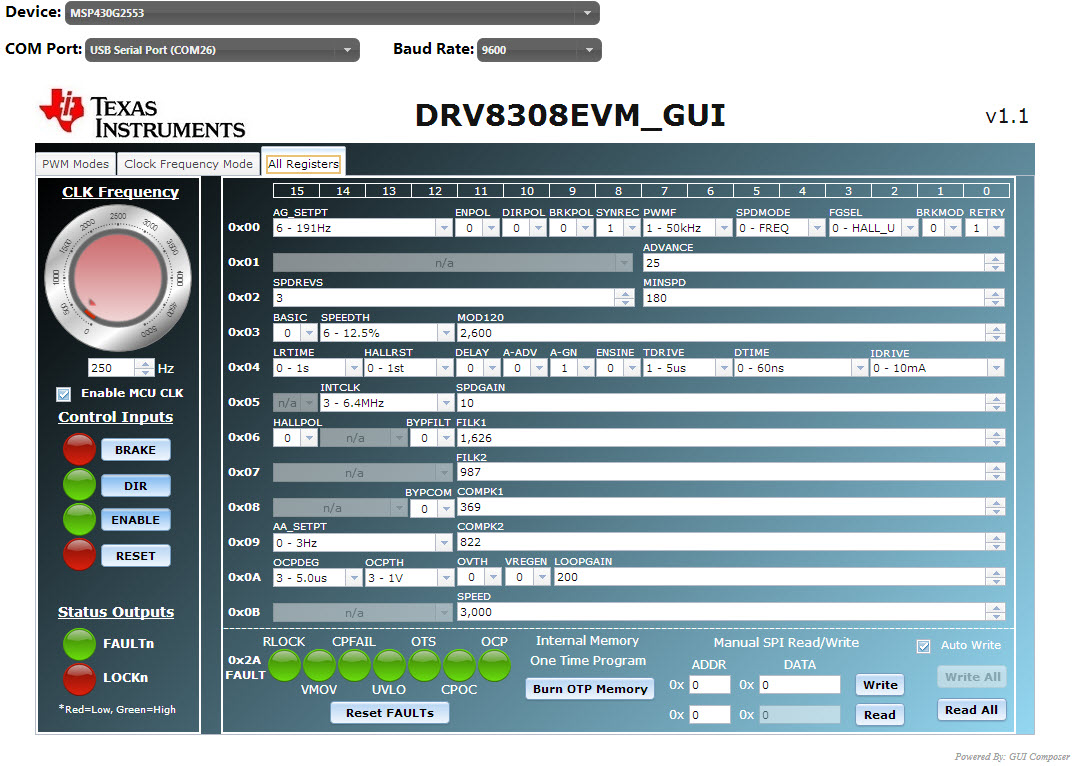
I'm using DRV8308EVM with GUIComposer (DRV8308EMV_GUI v1.1) in combination with a 3-phase BLDC motor (1 magnetic pole pair)

The "PWM Modes" works all fine. In the "Clock Frequency Mode" I'm able to start but the clock freq has no effect to the speed. Changing LOOPGAIN or SPDGAIN without any impact.

Any ideas I could check?

thanks, gmlo

  • Hi gmlo, you're on the right track, since you're able to spin but without speed control.  You're at Step 3 on Page 11 of the EVM User's Guide.

    First, try increasing the SPEED register to 4000, and toggle ENABLE to restart the motor.  If fCLK still doesn't match FGOUT, try increasing LOOPGAIN and decreasing fCLK.

    What is your target RPM and fCLK?  Make sure to set AG_SETPT to the closest setting to your fCLK.

    Are you using an external clock?  If so, make sure to disable the MCU clock in the GUI, or remove the bus isolation jumper.

    When you run in PWM mode, make sure that your motor spins well when DIR is Low and High.  If it only spins well with 1 DIR setting, the Hall sensor polarity might be backwards (which can be fixed with register HALLPOL).

    Let me know what you find.

    Best regards,
    RE

  • Hi RE

    The hint to increasing SPEED and LOOPGAIN and decreasing fCLK was helpful. Thanks. So, it's better to do first Step 3 and afterwards Step 2. Now the speed control works until about 200 Hz. More is not possible.

    My target is 15000 RPM with fCLK = 250 Hz. AG_SETPT  is set to 191 Hz. I'm using the clock signal from the MSP430. The HALLPOL is correct.

    To match FGOUT with the 250 Hz I tried changing the filters and the SPDGAIN without success. So I tried incrementing MOD120 with positive results. Is this the right way? Or could I check anything else before changing MOD120?

    I confusing about the SPEED register. Figure 21 of the DRV8308 datasheet shows that this register shouldn't have an impact while system is in "CLKIN mode". It should only have an impact in "Speed Reg mode". Am I wrong?

    Best regards,
    gmlo

  • You ask many good questions.

    If you're using sine mode (ENSINE = 1), then I think it's best to set MOD120 to 3970.  Increasing MOD120 increases gain similar to LOOPGAIN, so if you're getting better results with higher MOD120, you might also want to increase LOOPGAIN.

    The current datasheet inadequately describes the SPEED register, but the tuning guide covers it.  "SPEED - This is the open-loop gain during spin-up, before LOCKn goes Low. It simply must be high enough in order to reach the commanded RPM."

    So have you gotten fCLK to match FGOUT, which means speed is locked?  If you could attach a screenshot of the GUI, I'll take a look to make sure nothing looks out of line.

    Best regards,
    RE

  • I'm using normal mode. In this mode I already tried to increase LOOPGAIN with fCLK = 250 Hz without any impacts. So I incremented MOD120 until fCLK = FGOUT was possible. See attachment for more information.

    Thanks,
    gmlo

  • It's excellent you've gotten speed to lock.  At that point, you should be able to load down the motor with your hand and maintain the same RPM.  If RPM drops when doing that, then either:

    • LOOPGAIN should be increased,
    • The external power supply max current should be increased, or
    • VLIMITER is being reached on ISEN and a smaller sense resistor should be used.  The default on the EVM allows 5A.  If you're not using a current probe to see the actual peak current, keep in mind that if the power supply says the average current is 2A, there could easily be 5A peaks.

    All your GUI settings look good, but I would still prefer MOD120 = 3970 if that gives good results.  Its default of 2048 is needed for PWM modes to have a 1:1 duty cycle behavior.

    Once you have the closed-loop speed control working well, and with a good torque operating range, the next 2 things you may want to optimize are the startup profile, and the spinning flutter.  Registers LOOPGAIN, SPDGAIN, FILK, and COMK are the primary ones to tune.  As you go through that, use the "minimum total gain" methodology described in Step 4.

    Best regards,
    RE

  • Hi RE


    Thanks for helping. Now it works well.
    The next step was the schematic design. See attached file. I checked it and it seems to work correctly. However do you see anything I could optimize? Any possible challenges? Any hints?

    Regards,
    gmlo

    Motordriver.PDF
  • gmlo, I like how you put the block diagram into the schematic symbol!  Overall it looks fine, but I have a few comments:

    1. 100k is a large pullup; rise time on SDATAO and FGOUT might be slow, but maybe ok.
    2. You shouldn't need the series inductors, but they can help improve performance.  This device's VLIMITER provides an easy way of limiting startup current.
    3. I haven't tested tying FGINN to FGFB.  Leaving those unconnected is definitely ok.
    4. D1 is probably not needed, especially for your low operating voltage.  Sometimes a TVS can cause more problems than it prevents, as they sometimes fail and short.
    5. If the 220uF is reasonably close to the DRV8308, you don't need the 22uF.  It's good practice to place a small ceramic cap (100nF) close to the device.

    Be sure to send me the layout, and I'll review that also.

    Best regards,
    RE