This thread has been locked.

If you have a related question, please click the "Ask a related question" button in the top right corner. The newly created question will be automatically linked to this question.

DRV8307 Direction problem

Other Parts Discussed in Thread: DRV8307, DRV8307EVM, DRV8308, DRV8308EVM

Hello there,

I am currently developing an application which uses DRV8307 to drive Nanotec BLDC Motor DB42M03 (link http://en.nanotec.com/products/633-db42/ ).

Everything seems to be working but one thing: When I change the Direction by connecting DIR pin to VCC the direction is indeed changed but the motor drives slowly (I drive it with 100% PWM) and "coughs".

I really dont know what I am wrong. The way I change directions and stop now are (pseudo code):

// forward
DIR = LOW
BRAKE = LOW
ENABLE = LOW

// backward
DIR = HIGH
BRAKE = LOW
ENABLE = LOW

// STOP
BRAKE = HIGH
ENABLE = HIGH
break;

Here is a short video showing the faulty behavior. One direction spins correctly, the other one doesnt:

https://www.youtube.com/watch?v=eemiiEDQV3I

Heres the schematic of my controller, i drive it using an MCU powered with 5V:

https://dl.dropboxusercontent.com/u/14154631/mechatronic/BLDC_test_ctrl.PDF

  • Hi Lukasz 

    Are you change the DIR on the fly? 

    I believe you get an OCP condition when you change the DIR. And then your motor can't be driven and speeded up normally so the OCP condition not released, the motor just keeping "coughs".

    Could you try stop and braking the motor completely and then control the PWM duty from smaller one such as 20% and increase gradually to startup your motor to other direction.

    In another way you need to adjust the over current parameters for the shunt.

    Best regards,

  • Hi Wilson thanks for the answer,

    No I never change the dir on the fly. I always firstly stop the motor and then change direction. It doesnt matter if I do this from the start (power-up) or after some spins. It just seems that only one direction works correctly. I have tried spinning on like 30% PWM and other its always the same, one driection is OK, second is slow and coughing.

    I believe by OCP you mean overcurrent protection? What do you mean I need to adjust it?

  • Hi Lukasz

    Could you give the output U or V or W waveform during the direction it runs? What about the no load current?

    Maybe you haven't got the correct U, V, W sequence to this Hall sequence. There is still possible to run the motor in one direction.

    Best regards,

  • What you suggest might also be right- Nanotec, the motor producer names their hall pinout H1, H2 and H3 instead of HU, HV and HW. I tried couple combinations already (there are not many of them though) and this seemd to be working correctly.

    Documentation: http://en.nanotec.com/fileadmin/files/Baureihen%C3%BCbersichten/BLDC_Motoren/Product_Overview_DB22_DB28_DB33_DB42.pdf


    The screen capture at my scope works pretty bad so ill try to describe it: When I rotate in the good direction, the squarewave on HALLOUT pin is very steady. When I rotate in the bad working direction the squarewave is wider and changes a bit during time (getting tigther and wider)- Like there is no stable speed.

  • I have checked all 6 configurations for the hall connection. I got a pretty suprizing result:

    U V W Result
    1 3 2 X
    1 2 3 X
    2 1 3 X
    2 3 1 only right dir
    3 1 2 only left dir
    3 2 1 X

    There is not single right config. At one motor works only at right direction and at second one only at left... What could be wrong here?

  • Hi Lukasz

    Could you show the outputs U/V/W waveform in those two running condition?

    Have you ever change the motor winding from star to delta or reverse?

    Also please recheck all the Hall inputs signals, whether the pattern is what we expacted?

    Best regards,

  • I have only 2 channel scope but ill try to paste some images here tommorow. I have never changed the widing config. I have checked the hall connections several times and tried different configs as you can see in the table.

    Tommorow morning ill give the hall outputs.

  • Hi Lukasz

    OK. I just want to see any of the U, V, W phase output, the mid point of any of the half bridge. 

    Best regards,

  • Hi Lukasz,

    Please look at the site:

    http://us.nanotec.com/support/tutorials/stepper-motor-and-bldc-motors-animation/

    Once there, move the cursor over BLDC motors and select Block Delta.

    I think this information describes how your motor should work. Hope it helps.

  • Rick, thank you for the link. I have seen this animation erlier but I dont find it helpfull. I know how does the BLDC work. I am using a ready driver DRV8307 and all I do Is put on PWM and pick the position, the driver shuld drive the motor, but it doesnt. The problem lies on a different level.

  • Lukasz, I've seen very similar behavior when the Hall sensor polarity is swapped.  Then only 1 direction spins well.

    There's not a standard that all motors follow.  Some use "High" signals and some use "Low", with respect to the magnets being detected.  It's simply based on the Hall sensor mounting, because a 180 degree flip swaps the polarity.

    If you look at the DRV8307EVM schematic (http://www.ti.com/lit/zip/slvc565), the two conventions were accommodated.  When using a motor with differential Hall signals, it's easy to swap the + and -.  But for single-ended Hall signals, different biasing is required.

    Case 1: connect single-ended Hall wires to the + pins, connect pullups to the + pins, and bias the - pins with a middle voltage.

    Case 2: connect single-ended Hall wires to the - pins, connect pullups to the - pins, and bias the + pins with a middle voltage.

    Note that the very similar DRV8308 device has SPI configuration, and there's a bit for HALLPOL.

    Best regards,
    RE

  • Aha...

    Well, the problem is I only have H+ signals avaible coz i biased H- in the board design. But ok i gues I can cut some tracks and try it out. Thank you.

  • I also noticed C12 is probably too small.  It should be at least 1uF, and preferably 4.7uF.  Each time the real Hall signal switches, it tries to change the middle voltage, so more capacitance is needed for a stable middle voltage.  It's easy to measure.

    Best regards,
    RE

  • I see, ill change that right away, thank you for the tip!

    You know, in my application i need to use BeagleBone Black to drive 2 BLDC motors. As for now i wanted to use DRV8307 x2. Do you think i shuld swap to drv8308 instead and drive them only with SPI? Would you say that using SPI instead of driving them directly by DIR, ENABLEn etc is slower?

    I just started considering it since you showed me that the drv8308 is very configurable.

  • If you just want to spin BLDC motors, the DRV8307 is simple to use, offers protection and current-limiting features, and is for sub-20A systems.

    If you'd like to tune BLDC performance the DRV8308 is the right choice.  It lets you tune the Hall sensor delay, control motor current to be sinusoidal, and has closed-loop speed control.  Or you can also use it open-loop without a clock and just set SPEED to your duty cycle input.  The configurable gate drive current (IDRIVE) minimizes voltage noise when the FETs switch, or allows up to 100A systems with its highest 130mA setting.

    I wouldn't say SPI is "slower".  And with the DRV8308 you can still control DIR, ENABLE, etc directly.  The DRV8308 is footprint-compatible with the DRV8307 so it should be easy to migrate.

    Best regards,
    RE

  • Dear Fellas,

    Ive done the following steps in pursue of fixing the problem:

    I have biased all + inputs of the hall comparators to 2,5V.

    Connected each - input of the hall comparators to the Motor HALL sensor.

    In this configuration motor doesnt work at all... It spins back and forth, i tried every config of HU, HV and UW.

    Seems like biasing "munus" and using "plus" comparator terminals was correct. But the problem still stands- why does only one direction spinning works?

    An employee of Nanotec (Motor Manufacturer) couldnt help me, he said that there has to be something with the motor controll. Well i have posted the way i drive the DRV8307 in the 1st post.

    Do you have any other ideas :(? Im pretty clueless right now.

    EDIT:

    Also, here are the scope signals from HALLOUT when going in correct nad bad working DIR (I switched back the hal outputs to + and biased - of comparators):

    good:

    bad:

  • Lukasz, sorry to hear it isn't working.  There clearly appears to be a problem with the phase or Hall wiring, or the Hall polarity.  For the trial-and-error approach, the DRV8307EVM has 2 jumpers that make it easy to try each Hall polarity.  Or if you can get more documentation on the motor, you could see whether each Hall signal is High when the corresponding phase is High.

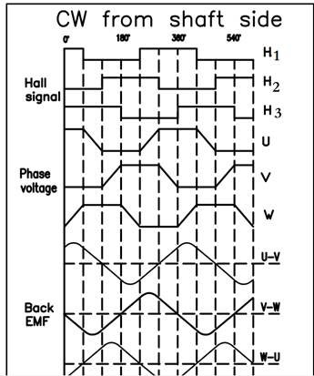
    For example, if you download this and open the TelcoMotion PDF, on the left side is a commutation diagram.  HallA ("HA") corresponds to Phase U, and HB to V, and HC to W.  When Phase U is High, HA is Low; this is the "Inverse" convention, where you need to bias the + pins.

    Btw, HALLOUT has the same frequency and phase as HALL_U.

    Best regards,
    RE

  • I just got the commutation diagram for the motor im using from a Nanotec employee:

    It seems that the conversion is consistent, not inverse. So I shuld bias the "-" terminals and use "+" ones like I did. The problem stays unresolved :/

  • I agree.  Based on this, DRV HALL_U connects to H1, HALL_V connects to H2, and HALL_W connects to H3.  It's "normal" polarity where you'd bias the negative pins.  And of course, the phase letters should map directly between the DRV and motor.

    I wonder if there's a bad connection or bad sensor to blame.  If you haven't already, try turning the motor with your hand and verify the Hall signals toggle on the DRV PCB.  Verify the 2V bias is present on the - pins, and that the + pins see the voltage swing.

    I've tested many 3-phase BLDCs with the DRV8307.  Getting the wiring right can sometimes take a lot of tries...in your case the only thing I can think of is a connection problem.  If you have a 2nd motor and board, it would be valuable to see if the problem persists on those.

    Best regards,
    RE

  • Now when you said it, I also think it has to be motor connection problem, take a look at the table again that i have posted:

    U V W Result
    1 3 2 X
    1 2 3 X
    2 1 3 X
    2 3 1 only right dir
    3 1 2 only left dir
    3 2 1 X

    According to this HU connects to H2, HV to H3 and HW to H1... And only for one direction. The only way to solve this issue is as u suggested getting another motor to test. Thank you for help, ill keep you posted.

  • You can use the DRV8308EVM as a reference.  If you buy it, it comes with a motor, and wiring is described in the User's Guide.  If you just want to buy a motor by itself, the Anaheim Automation BLY172S-24V-4000 is extremely similar, but it's only $20 cheaper than the EVM kit...there are also some $59 motors on that webpage.

    Best regards,
    RE

  • Thank you for the link, ill have a look into it!

  • Hello again,

    I have tested the motor using PIM2403 driver from technosoft: http://www.technosoftmotion.com/en/

    I can drive the motor without any problems using their software. It seems that the problem lies in DRV8307 circuit. Would you have any other concerns regarding my schematic or way of driving the lines?

  • Hi Lukasz, I'm fairly confident your DRV8307 system has a connection mapping or bad-connection issue, because nothing else would explain why 1 direction works fine, and using a different controller also works fine.  I'm going to look into your connections some more and get back to you.

    Best regards,
    RE

  • Thank you,

    The thing is that in my app the motor only works in hall config that doesnt match the way ot should be connected. Thats what is so weird for me.

  • Hi RE, any news?

  • Yes, I've been looking into this today.

    If you start with completely unknown/unlabeled wires, you can determine the Hall-to-phase mapping by following the technique described in this blog.  Those steps basically involve:

    1. Assign each phase wire to A, B, C.
    2. Connect a power supply positive terminal to A, and negative to B and C, forcing about 1A.  Now measure the Hall signals; the one that's not like the other two is Hall C.
    3. Disable the power supply and connect the positive terminal to A and B, and negative to C; enable the supply.  The Hall signal that changed since Step 2 is Hall A.  The last remaining one is Hall B.

    Now, connect A/B/C phases and Halls to the DRV8307 U/V/W phases and Halls.  There are 6 combinations, and 3 of them are correct (assuming a correct Hall polarity).

    In this spreadsheet I tested each combination: 3441.DRV8308 connection tests.xlsx  (Regarding "chops at single-Hall", the DRV8307 first uses all 3 Hall sensors until a constant speed is reached, and then switches to use 1 Hall for better jitter performance.  With improper connections, the motor will spin for a half a second and then get messed up upon switching to 1 Hall.)

    When you experimented with your PIM controller, what was your power supply current?  And what was the power supply current when you spun with the DRV8307 in the direction that spins?  If the DRV8307 case was 5x higher current, then based on my spreadsheet, it appears you're on the right-side column and need the opposite Hall polarity, along with changing mapping.

    Best regards,
    RE

  • RE,

    I am not sure what current was flowing through the motor when used with DRV8307, but I can tell it was high because once my AC adapter (24V and 10A) went down.

    As for the PIM driver the current was set to about 5 A.

    This situation is weird to me bacause I have cheched all 6 hall combinations in both polarisations (+ and - biased). When biased the +, none of the hall configs were working correctly. And when the - was biased, I got 2 configurations working (like posted before) but for each of that working config only 1 direction was spinning correctly.

    So I gues I need to bias the "-" as I did on the beggining, the commutation diagram later on also confirmed this. Thank you for the link, but as I said I have checked every single config :(.

    Also i feel like HALLPOL is a parameter from DRV8308, so by changing it do you mean biasing the other comparator input in DRV8307?

  • Would you be able to ship your motor to me in Dallas, TX?  I can check it out with my DRV8308EVM and figure this out.

    Setting HALLPOL=1 is just like biasing the + pin and wiring to the - pin.

    Best regards,
    RE

  • Nanotec has lend me their used, tested motor that will arrive this week. If it wont work as well, I will discuss this with my boss. Thank you a lot for your commited help.

  • Hello RE,

    I have tested the driver with another BLDC motor sent from Nanotec and the behaviour stays the same, actually not quite. The motor i tested now is DB24M02. Only 1 direction works at a time, but the table looks different now.

    U     V     W     Result
    1     3     2     X
    1     2     3     X
    2     1     3     only left dir
    2     3     1     X
    3     1     2     X
    3     2     1     only right dir


    I am so confused right now :|.

    We are wondering now either to buy the DRV0308EVM board, but if there are no flaws in my board the behaviour will probably stay the same. Do you have any ideas now RE?

    Also I would have one more question regarding the BLDC- After some lecture about them I am not sure either it is possible to stop the motor in between the poles. What I mean is, we would like to be abble to drive the motor very precisly (about 40 microns) and keep a sufficient speed (Move the portal the motor is attached to about 50cm per second). The question is, is it true that the minimum BLDC motor step is 1/6 of the circle? In that case we would need to use a bigger ration on the motor, which would improve the motor resolution but drasticly lower the speed. If a BLDC motor would be able to stop more precisly (like stepper motors can do microsteps) it would not be a problem.

    We have an encoder attached so we can make a driver that would drive the motor if thats the case.

  • Lukasz, sorry for the delay, as I was on vacation.  And sorry to hear it's not working!  Is it at all possible for you to ship me a motor?

    It sounds like you want to spin the motor at a consistent speed, with less than 40um of position error.  Can you describe this in terms of jitter percentage?  I've used a flutter meter with the DRV8307 to drive BLDCs with <0.5% jitter, and a tuned DRV8308 can achieve <0.1% using speed control.

    In general, it may be feasible but it depends on the motor being used.  Some BLDCs (like computer fans) have lots of cogging force where they snap into certain positions, based on the poles and windings.  Others have no perceivable steps, where it's far more than 6.

    Best regards,
    RE

  • Hello RE,

    We have orfered our own drv8308evm from digikey, it shuld be shipped soon. I wouldnt like to bother you with the motor if its not neccesary, I hope i will find everything out with the evaluation board. If the motor wont work even with the eval board i would ask for help again.

    Thank you for the explanation of the spinning. I cant really talk abou what jitter we are interested in yet but 0.1% sounds more than enough.

    I already aprichiate your help a lot. I hope i will make this nanotec motor work using the board.

  • Hello RE,

    The DRV8308EVM from Digikey just arrived, but there is no motor in here! You caid that it comes with one tested motor. Did they forget to add it or did I misunderstood something?


    EDIT........

    I just noticed I ordered DRV8307EVM instead of 08... No we need to make a return, but will the DRV8308EVM feature motor as well?

  • The DRV8308EVM comes with a motor, while the DRV8307 does not.

    Best regards,
    RE

  • Ok, ill hope we can exchange it now.

  • Would having the motor really help solve your problem?  Both EVMs can allow you to quickly try many different wirings.  However, with the 8307, to try different Hall polarity you move a jumper and change 3 Hall wires, whereas with the 8308 you just set a register in the GUI, so the 8308 is a little easier there, but both can get the job done.

    Best regards,
    RE

  • For this matter it doesnt make the diff, but as you said before drv8308 has a lot better tuning features and we will need that. Also I need to see the refference motor spinning.

  • Lukasz, have you had any success with the DRV8308?  I was thinking that maybe this motor's Hall sensor placement is optimized for 1 direction, causing the other direction to have too much phase shift.  Register ADVANCE could fix that.

    Best regards,
    RE

  • Hello RE,

    I have a lot of work right now and the evm8308 is on my desk waiting in queue... Nanotec employee never mentioned about the single direction optimalisation but as soon as i get started with testing the module ill keep in mind the advance register. Thanks you for the hint.

    As soon as i get it working/ not working ill give feedback.

  • Ok.  I might try to obtain one of those motors too.

    Best regards,
    RE

  • That would be great as well, thank you a lot.

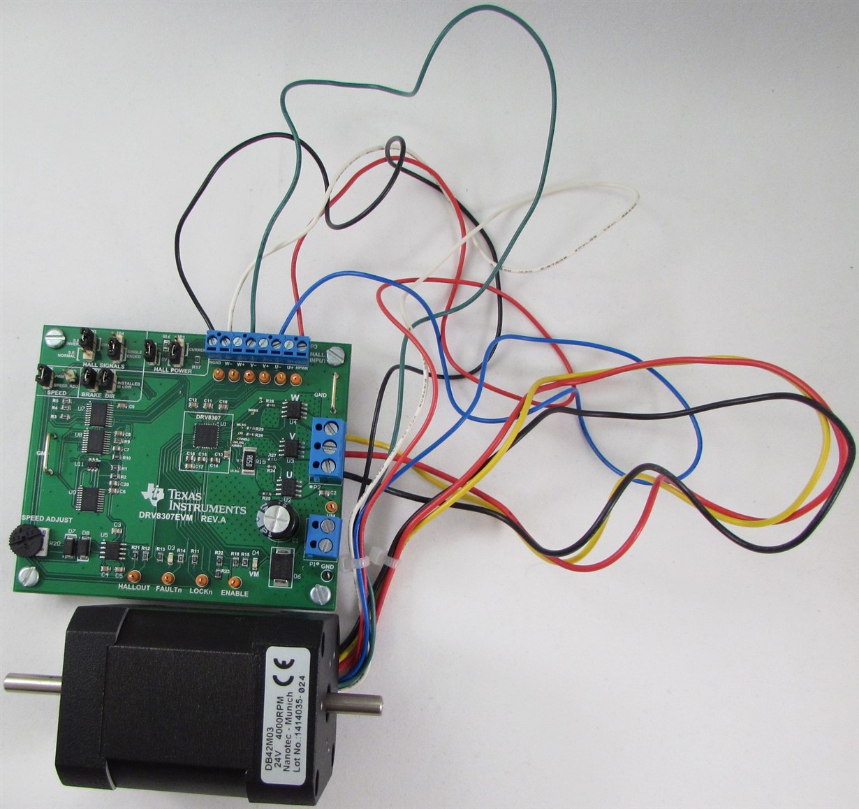
  • Hi Lukasz, I bought your same motor (Nanotec DB42M03), and got it to work perfectly with the DRV8307.  It took me a few tries with the phase wires to find the right mapping; here it is:

    Pay close attention to the Hall inputs being connected to the "-" pins, and the Hall jumpers are set to Single-Ended Invert.  Have you tried this?  The DIR pin also works properly, where I can pull the jumper while the motor is spinning, and the motor will stop and re-start in the opposite direction.  Also make sure your power supply is set to 12-24V and at least 1A.

    Best regards,
    RE

  • Hello RE, Thanks for the support! Ive been overloaded with other topic and had to move this one aside- but i still have to deal with it. As soon as I get everything else done and start working with this motor ill threat your post as refference! Its good to know it works, but tbh when I think of it now I dont know why didnt it work for me. Ill try to get onto it as soon as possible. Thank you again.

  • Hi RE,
    I have the very same drv8307EVM board and I'm halted in my development as I experienced 2 different situations (both faulty):
    Supply : set at 15-20V and 3 A limit
    "situation 1":
    When I received the board I connected it like yours , except for that the hall sensors were connected to the "+"pins single ended non-invert.
    When powered, the circuit took about 0.3 A. The motor did run discontinuously (run-hic-run-hic... -> hic is a brief stop). This is not how bldc's should run, so I played around with the jumpers but nothing changed, and finally returned the jumpers to the original discontinuously working positions. I repeated this with each time cutting off the power, and re-powering. Then I did cut the powered again and for no apparent reason the motor started behaving differently (no turning back to the previous behavior... This is what I call the "situation 2".
    "situation 2": This new situation or behavior is as follow:
    I power the circuit.
    motor runs continuously, but it lasts only a few seconds, and then the motor halts and D3 (Faultn) lights up. After a few seconds, D3 goes off, and then the motor might restart again for a short period and dies again, lighting up again D3... D3 might go on and off a few times, but at the end it dies as wel. And I am left behind with a dead DRV8307 and motor...

    After this devastating experience, start looking in the documentation / datasheets and find under 9.1.1. in the datasheet, the trick with the resistors. I adapt the circuit accordingly, but "situation 2" remains. Nothing improves.

    Then totally desperate (just before wrapping the rope around my neck, not to face total disgrace), I see your post and regain hope. I rewired again and set the jumper, as you did, but the situation doesn't change...Total disaster...

    Of course, i did some measurements as well and here is my conclusion over the different settings and situations:
    1) Not two different hall sensors have the same amplitude(20 to 50% of the biggest value). All within the maximum range of VREG. The differences remain whether I take the "-", "+" or GND as reference. In my previous experiences(life), the amplitude of the hall sensors were all alike...
    2) The output of U,V,W during the "motor running" instances, measured referenced to GND, suffer from the same disease, as not two shapes are alike and recognizable as the shape mentioned in the books, I would expect from a no-nonsense bldc drive. Amplitude is within expected range, but the view is a real carnage.
    3) I also tried different bldc motors with the same results.

    I had expected to use this controller for driving, braking (also chopped) end in regenerative mode to recover or dissipate energy. But so far it is only breaking my dreams and my hart....sprinkle...

    What now ? Change religion, from "TI" to "Allegro"? What have I done wrong to the TI god?
    Can someone help me with a suggestion or more? Other than becoming a painter, a priest or ...

    By the way, how can I post a picture here that might help illustrate the situation.

    Kind regards,
    Francisco
  • Hi Francisco,

    Sorry to hear of the problems you are experiencing.

    Posting a picture would be helpful. To do so, please click on the "Use rich formatting" once you have selected Reply. This will bring up additional options to change the font, add files or pictures, and add hyperlinks.

    In addition, can you provide the specifications of the motor?

  • Francisco, let's see if we can recoup some of your losses in the aftermath of your terrible devastation.

    Your BLDC motor's Hall sensors most likely have an open-drain output. You could verify that those Halls are still functioning correctly by putting the DRV8307EVM aside, applying PWR/GND to the red/black Hall wires, connecting a pullup resistor for a Hall signal to some voltage, turning the BLDC with your hand, and observing toggling from the signal.

    If that works, next we want to explain why you're getting different high voltages from the 3 Hall signals when the motor is connected to the board. If I had to guess, I'd say make at least 1 FET switch might have gone bad (U7, U8, U9). Try removing U7 and U8, and wiring HU+ to a pullup by connecting a wire from the top of C10 to the bottom of R5. You can then test the Hall voltage swing by disconnecting the motor phase wires from the board, powering the board (which powers up the DRV8307 as well as VREG), turning the motor with your hand, and observing the Hall signal swings the full voltage. If it doesn't, that would suggest an input to the DRV8307 may be damaged (that's unlikely).

    Maybe you can get up and running by removing U7 and U8, adding 3 wires directly to the pullups, and trying different Hall combinations. I've seen some motors that required swapping Hall "U" and "V" signals.

    Best regards,
    RE
  • Thanks very much for all your replies,

    Meanwhile I discovered that the hall sensors on the motor are broken (measured separately). this must have happened as I was messing up with the jumpers, and the motor (+ driver) started to act differently.  Sensors on the motor are definitely broken (different voltages under 4V), don't know yet about the board. I'll come later on this... And yes maybe the switched are gone too ??? Can his have happened because of changing jumpers???

    Best regards,

    Francisco

  • > different voltages under 4V

    Keep in mind that the Halls are probably open-drain outputs, which should always be Low or High-Z.  When you say 4V, that will depend on your attached pullup resistor and pullup voltage.  If you're pulling up to 5V and use a 1k resistor for example, and measure 4V, that would imply that the Hall output has a 4k resistance to GND (making a voltage divider).  I think that would be strange, so double check that.

    Best regards,
    RE