Hello,
pls send to me what the pwma, pwmb waveforrm should look like for cycle-by-cycle mode. i am using pwma 97%, duty cycle and pwmb zero (off) and cycle-by-cycle works perfectly!! why does it work if i am suppose to give pwmb 1% signal to refresh bootstrap capacitor? It works under no load conditon (meaning the output pwm signal matches the input pwm signal) and for a 5 ohm power resistor as my load ( pulling some 5 amps). my pwm is running at 28kHz and bootstrap capacitor is 100nf / 50v for my dual full bridge and for my parallel full bridge my bootstrap cap is 2.2uf / 50V and i do not place the recommended 5ohm resistor between 12vdc and GVDD-X pins. so why does my parallel full bridge work ok without this 5 ohm resistor? what future problems can i expect because i not have this 5 ohm resistor?
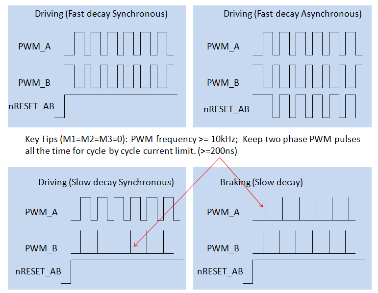
If i change the pwmb from zero to 1% duty cycle while the pwma is running at 97% dyty cycle when should the pwmb pulse go high in relation to the pwma pulse? should pwmb pulse go high when the pwma pulse goes low? do they have to be at both same frequency? in syn?
also my new pcb has the optional Stuff Option capacitors just like the TI evaluation pcb but they keep exploding when i activate the pwm. why? i thought i needed them for my piston load ( with self monitoring current shut down circuit inside ) but when i remove them i can still work ok. why?
-Steve