This thread has been locked.

If you have a related question, please click the "Ask a related question" button in the top right corner. The newly created question will be automatically linked to this question.

faults occrured in using InstaSpin BLDC & DRV8313 for a new sensor less BLDC motor design

Other Parts Discussed in Thread: DRV8313EVM, DRV8313

Hi,

  We are using DRV8313 for a new sensor-less BLDC motor with instaspin software on MSP430.

  From time to time, the motor would stop and the variable (in MSP430 firmware) Fault_8313 was set to 1.

  Here are my questions:

  1. What conditions would cause variable Fault_8313 being set?  Is there anyway to find out more information about cause of faulty conditions?

  2. For now, we can only stop and start the motor to resume operation.  Is there any other more graceful way to recover from such faulty conditions?

  We did use a bench top power supplier to provide power to the system to reduce any possible effect from over current or over voltage.

  With the same BLDC motor, we did try to set up DRV8313EVM with "TI DRV8313 EVM" PC software and the same faulty condition did occur too.

  • Hi Chiwen

    Have you checked the nFAULT pin voltage of DRV8313 when this fault happened? We may need to identify whether there is a hardware fault happened first or an algrithm fault because of miss- matching the motor parameters.

    What is your motor parameters? is there a spec of the motor?

    When you use DRV8313EVM, did you just using the GUI and unchanged firmware of the MSP430 or use your own program? 

    Best regards,

  • Hi Wilson,

      nFAULT of DRV8313 is low (~0V) so it seems that it is a hardware fault.

      We are using a 12-pole BLDC motor.

  • Wang,

    So it's clear that fault is occuring in Hardware, mostly due to over-current  or under-voltage condition. Most probable reason could be that Flux thersold is not tuned properly.

    I would suggest you to use EVM and tune it properly, as explained in EVM user guide.

    Best Regards

    Milan-Motor Application Team

  • HI Milan,

      Thanks for the suggestion.  We did follow your suggestions and use DRV8313 EVM to tune the flux threshold.  After some tuning, the hardware fault condition hasn't happened since.

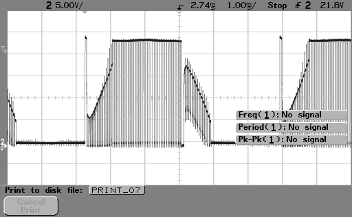
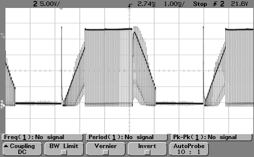
      However, when we tried the same tuning procedure on our PCBA, we encountered another problem.  We can tune one winding U properly but the other two windings, V & W, didn't work well and still exhibit "unsymmetrical input waveform" when we measured input voltage.  BTW, our PCBA pretty much follows DRV8313EVM's design but has a different form factor and layout.

      Attached are scope screen shots of U, V & W input voltage measurements.  Do you have any idea what may have gone wrong?

    U winding

    V winding

    W winding

  • Chi-wen,

    Looks like there is some-offset  in back-emf sensing.

    Can you re-check back-emf sensing resitors values (95K and 5K) of all three-phases and Vdc, all values should be witin +/-1 to 2%.?

    Also if you are using any caps in 3-back-emf sesing across 5K resistor you may remove it and try re-tuning flux thershold. Don't remove cap of Vdc sensing, only remove across phase if any.

    Best Regards

    Milan-Motor Application Team

  • Hi Milan,

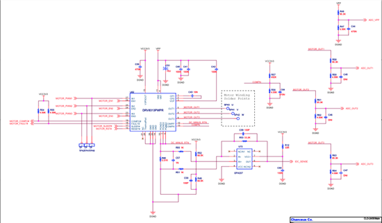
      We use 95.3K (1%) and 4.99K (1%).  The capacitor across 4.99K is DNI (Do Not Install.)  There is a 470N capacitor across 4.99K on VDC sensing.

      Attached is the schematic drawing of DRV8313 related circuitry in our design.

  • Chi-Wen,

    Ok I see, Your schematic is right  but Typically there would exist small mismatch between 3-phases voltages due to component tolerances & variation in motor stator impedance between phases.

    I'm wouldn’t say that mismatch can be completely removed, but definitely We can try our best to reduce it as much as possible. So let do following:

    1. As I understand from waveforms, you have tuned the flux threshold taking U-phase voltage as reference. Lets take V-phase as base and try retuning the flux & see if unbalance reduces.

    2. Sometime particular motor sample may contribute to unbalance, I would suggest to try few other samples.

    3.  If both of above give same results & it is confirmed that different motor does not affect much: we can try put small filter in back-emf sensing. I know earlier I suggested to remove caps, but  If you closely look V & W phase voltage, you will observer little higher noise during negative slope, as compared to U phase. You can try adding 100pf/470pf/1nF across all phases to see if it helps. Start with smaller value first.

    Best Regards

    Milan-Motor Application Team