This thread has been locked.

If you have a related question, please click the "Ask a related question" button in the top right corner. The newly created question will be automatically linked to this question.

DRV110 solenoid drive inversion issue

Other Parts Discussed in Thread: DRV110

Hi Folks,

We are using the DRV110 to drive Solenoid coil.

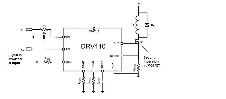
The requirement is that the Input and Output waveforms to be in-phase with each other. In order to achieve that  we are inverting the input to DRV110 and other inversion will be there in the MOSFET side. Please refer the below Circuit for reference.

 Inline image

Since we are inverting the Input Signal, the Logic is completely inverted i.e to Drive the Solenoid HIGH, the Input has to be "LOW" and Vice versa. 

DRV110 Input and Output are in phase. But we require the Trigger Input and MOSFET Output to be in phase.  To achieve that we are inverting the Input Signal. Since we are inverting the Input Trigger Signal, the Logic is completely inverted i.e to Drive the Solenoid HIGH, the Input has to be "LOW" and Vice versa

Please provide us suitable solution to resolve this issue.

Thanks,
Srijan

  • The picture is as above for ths post

  • Hi Srijan,

    I am notifying our experts on the device.

    While waiting, can you clarify your post? Did inverting the input produce the desired result? What issue would you like resolved?

    Thank you.
  • The requirement is that the Input and Output waveforms to be in-phase with each other. In order to achieve that  we are inverting the input to DRV110 and other inversion will be there in the MOSFET side. Please refer the below Circuit for reference.

    Since we are inverting the Input Signal, the Logic is completely inverted i.e to Drive the Solenoid HIGH, the Input has to be "LOW" and Vice versa. Please

    provide us suitable solution to resolve this issue.

    Srijan

  • Hi Srijan,

    Sorry, I am still confused. Can you describe what you would like using a truth table?

    Based on what you have said the current truth table is:

    /IN (input to inverter) EN (output of inverter connect to EN) OUT SOLENOID/FET junction
    0 1 on GND (0)
    1 0 off Vs (1)

    It appears that comparing /IN input to the SOLENOID/FET junction is in phase as you desire.

    Please clarify. Thank you.