This thread has been locked.

If you have a related question, please click the "Ask a related question" button in the top right corner. The newly created question will be automatically linked to this question.

DRV8832 fault pin problem

Other Parts Discussed in Thread: DRV8825

Hi,

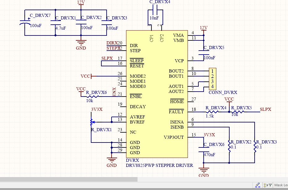
we are using drv8825 drivers for controlling NEMA 17 stepper motor. However, we have an important problem with the fault interruption which the driver internally has, because it turns down when we try to move the motor. We have read a lot of posts which talk about the same problem, but we have not still found the solution. What we have noticed:

- Fault pin turns down faster with 12 V power supply than 9V.

- The current which is supplied to the motors (VMA and VMB) is approximately 0.07A. This value does not change with the potenciometer.

- During some tests, the circuit has a strange behaviour. When the motor is enabled with a 12V supply, the fault pin turns down. However, when we reduce the supply until 5 or 6 V (at this voltage the driver does not work) and then fix it to 9V, the current increases, and this can be managed by the potenciometer. However, the current value does not achieve the expected value (with the reference voltage equal to 3.3V and with 0.3 Ohms sense resistors, the current was only 0.5 A instead near from 2A expected) and the stepper motor tries to move, but not correctly (a lot of little movements in the two directions). This was during some test, but now the circuit behaves as described in the point before.

I have attached two photos: driver schematic and driver layout.

I keep waiting anxiosly for answers :)

Thank you very much and cheers,

Antonio

  • Hi Antonio,

    Do you have the ability to capture the current in one of the motor windings? Is so, can you capture this and provide it to us?

    One note from the layout snippet is that the thermal vias appear to be too large. This can cause the solder to wick out of the hole to the bottom of the PCB and negate the effects of the vias. Please refer to the DRV8825 for a recommended thermal via pattern or you go to the Quality and Packaging tab of the DRV8825 page for a generic schematic and layout.
  • Hi Rick,

    Thank you for your reply.

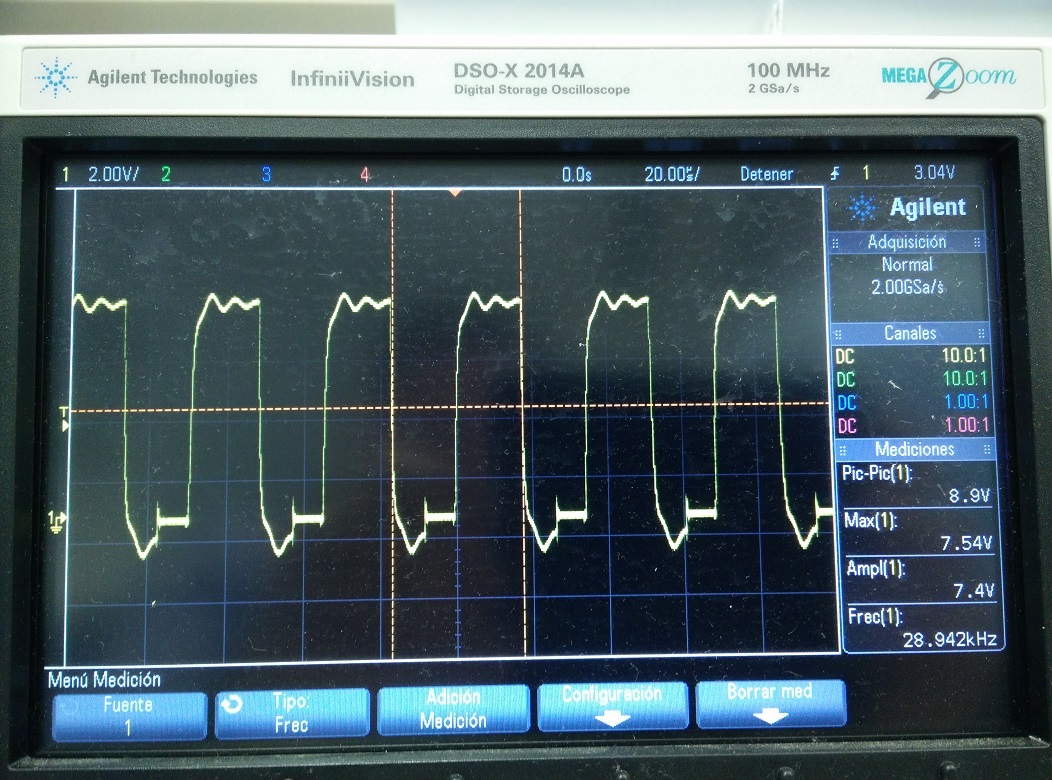
    This is the waveform in one of the motor windings. It was measured by using a 10 Ohms resistor in series, so it is actually the waveform in the resistor. I tried to measure directly on both terminals of the winding but it was impossible since FAULT is set low as soon as VM is higher than 8V (sooner than yesterday).

    Regarding the thermal vias, my manufacturer cannot provide us a smaller size. Any other idea?

  • Hi Antonio,

    Would you provide some details about this measurement?
    Is this after the device has been enabled and prior to issuing a step command?
    What is VREF at this point?

    What is the period of nFAULT?
    Also what are your motor parameters (V, R, L)?

    We are checking into the best approach for thermal based on your comments. Hope to have that information soon.
    Please confirm the thermal pad is soldered to the PCB to the best of your knowledge.
  • Hi Rick,

    answering your questions, the picture indicates the voltage drop on the 10 mOhms resistor, so the current intensity is proportional to this graphic. This voltage is obtained when the driver is enabled and it is receiving pulses in the step pin. The Vref was approximately 1.5V. We have tried with different motors ( 1ºmotor 83oz-in, 2A, 1.4Ohm | 2º Motor 2.5oz-in, 670mA, 6.8Ohm), both were tested with an Arduino RAMPS and pololus A4988 and they work perfectly. About the thermal connection, we have checked and we think, it is working, but we are not 100% sure since we can not measure it in any form.

    I don't understand, what you mean about nFault period.

    We have soldered a new driver in our pcb. Using Rsense of 300mOhms, the driver worked correctly and the stepper motor was moved. Also the potentiometer worked as normal, and we could control the driver current. We observed however, that the maximum available current was 700mA, so in order to achieve higher values, we changed the Rsense to 100mOhms. From here, the driver started to fail and now it behaviors as the first driver, with problems on Fault pin and the driver current. Also we have changed the Rsense to 300mOhms again, but its behaviour does not change. At summary, now both drivers do not work.

    Antonio
  • Hi Antonio,

    user4315025 said:
    I don't understand, what you mean about nFault period.

    The nFAULT will either toggle, indicating thermal shutdown or latch indicating overcurrent.

    Does the device begin working again if you lower VREF by a factor of 3?

    If at all possible, the best information that you can provide is a scope capture similar to Figure 8 of the DRV8825 datasheet. Even if the current does not look like this, the step command vs current provides a lot of information.

    Our experts had the following recommendations regarding the thermal vias:

    Either plug or tent the vias if they remain located where they are, or
    place them on the PCB metal area adjacent to the exposed
    pad that is covered by soldermask, so they are not exposed
    to the solder.

       However, if the via diameter is larger than 0.5mm, tenting
    should not be the solution as the soldermask is not well
    supported and could crack and open during reflow.

       Often a "dog-bone" approach is used to get the vias
    away from the package area, but in this case as Rick mentions
    all is needed is to move the vias to the area past the 5.18mm
    opening, locate them as shown below in red.

       But they need to make sure that the soldermask opening on
    the exposed pad is not larger than what we recommend and that
    as much paste as possible is applied on that area to ensure
    that the solder will remain in that location and properly wet.
    We have not seen their paste pattern to gauge that.

       Also have them check how good the solder joint is to pin 28,
    (GND) as it is directly on a metal pour, and soldering in that
    area will be controlled by the soldermask opening, which we
    don't see.

  • Hi Rick,

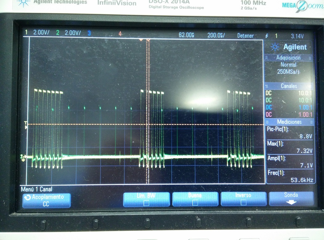
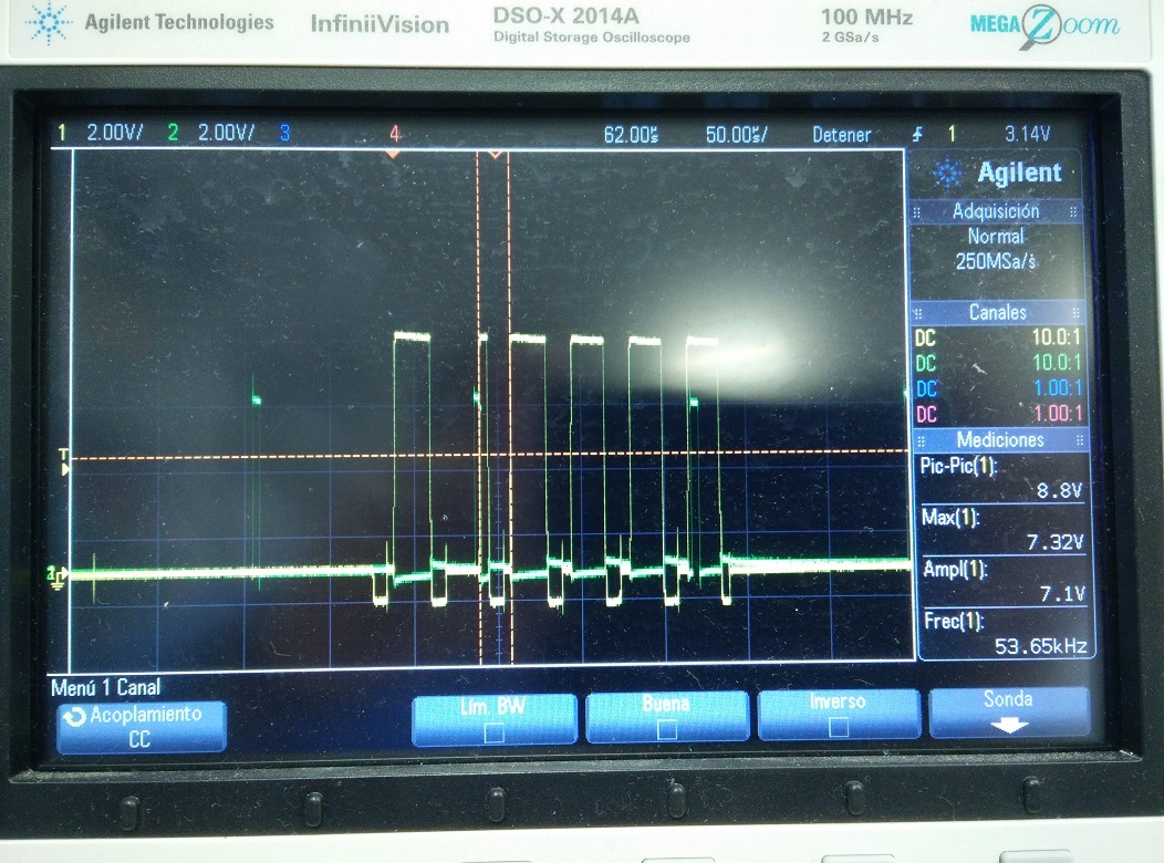
    This is current in one winding (yellow) vs steps (green).

    Fault is set low when connecting stepper motor directly to DRV8825. However, it remains high when we use a resistor (10 Ohms) to measure the current in the winding. In addition, DRV demands more current (we have to limit the current at 200 mA in order to avoid 10 Ohms resistor crashing). The problem with FAULT seems to be related to overcurrent more than overtemp. DRV demands a lot of current with 10 Ohms resistor is series with the winding (1.8 Ohms), so it will demand even more current without resistor (only 1.8 Ohms of the winding). Could it be caused by a wrong behavior of sense circuitry? I mean Rsenses are not working correctly, maybe due to residues from soldering-desoldering. I remind you that DRV worked fine the first time with 300 mOhms sense resistors and then, we changed them by 100 mOhms resistors and it didn't work anymore, even changing again by 300 mOhms.

    I hope this information can be useful for you.

  • Hi again,

    Another remarkable point is the fact that AOUT1 AOUT2 BOUT1 BOUT2 are sometimes shorted between them. It remains like that until I touch one of the A/B OUT and PIN 1 of the DRV (connected to PIN 2 by 10 nF capacitor) with multimeter (mode short circuit detection).

  • Hi Antonio,

    Sorry for the delay getting back to you.

    This appears to be either overtemp or undervoltage based on the scope captures. The reason I say this is overcurrent requires either nRESET toggling or a power cycle. If you are not performing either of those, overcurrent can be ruled out.

    Overtemp disables the outputs, but does not reset the indexer logic. So every 32 steps the outputs should reverse.

    Undervoltage appears to be the most likely candidate. Can you measure the voltage on the VMA/B pins when running to determine if the voltage is drooping below UVLO?

    The sense resistor should not be a problem. We have used .1 and .25 Ohms on various boards with no issues.

    To the last point about AOUT1/2 BOUT1/2 are shorted. Is this occurring when the nSLEEP is issued? If so, this is because the high side outputs will turn on effectively shorting the windings until VCP discharges. If this is undesired, placing a 1MOhm resistor across the charge pump capacitor will correct this. This resistor is shown in the most recent datasheet.

    Finally let's try the scope captures one more time without the series resistor. Please capture AOUT1, AOUT2, STEP, and VM at the pin. Next please capture AOUT1, AOUT2, STEP and nFAULT. I hope this will lead us to the issue.
  • Hi Rick,

    Sorry for the delayed reply.

    The problem may be solved. We were testing the driver and we realized that one via was not contacting as it should. This fact could have caused an asymmetry on sense currents and it might explain the wrong behavior.  

    Now we have other issue. Sometimes, the motor (Nema 17) makes noise (more than normal) when current is higher than 300 mA and it is enabled and not moving, only sometimes. Could you please help us with this trouble?

    Thank you in advance.

  • Hi Antonio,

    Glad to hear you have the motor running. When you say sometimes the motor makes more than normal noise, can you determine which step in the indexer the motor is? You can monitor the nHOME signal and count the number of steps after nHOME.

    When the motor is static you may not need as much current to hold it in place. Can you consider lowering VREF when the motor is static? A simple circuit is to add a parallel resistor using a GPIO control to lower VREF.
  • Hi Rick,

    At this moment, we cannot monitor the nHOME signal because DRVs are integrated on a PCB which is attached to a machine. Because of that, to add a circuit is also not possible. The unbearable sound just starts when motor is enabled and static after moving.

    What is really strange is that current consumption is higher when motor is static.

    Cheers.

  • Hi again,

    Do you think the DRV might be at one step in which the current is high and that is why it makes noise? For instance 45 degrees. Would there be any possibility to set home position using the nHOME pin?

    Thank you in advance.
  • Hi,

    When you say the current is high, do you mean by the power supply current (total average current)? If the two phase current are well regulated, at low running speed(rule out the affect by motor's BEMF), you should see an almost constant current from power supply, no matter which step is taken. Note that a litte vary of the current at each step is normal because the combination of the two phase current could have some error to our setting level. Otherwise, if you see big different of the current at each step, there could be something wrong with the motor phase current regulation.

    Also please alway note the value of phase current Peak/RMS will be greatly different to the power supply current. Usually the phase current is several times higher than the power supply current. And all our setting and regulation formula is refer to phase current.

    The home position can not be set to other angle. nHOME is an output.

    So, please refer to the following precedures to check the problem.

    #1. For the current level issue.
    Please try to record the power supply current at each step, and compare how much variation it has. If big differece is found, you can set the decay pin to High(fast decay), and then test the power supply current at each step again.
    #2. For the noise issue.
    There will be hiss type noise when the current is chopping. Also it is true that the noise pattern or level will be different at each step. Because the current level is different at each phase in different micro stepping step. The VM level, motor inductance/resistance, current level setting, decay mode will all have the impact to the noise pattern and level. Mixed decay usually gives the good current regulation with lower noise (Already used). In most case, we will get the noise level acceptable when the current is under good regulation. So let us make sure #1 current level issue is cleared first.

    Best regards,