This thread has been locked.

If you have a related question, please click the "Ask a related question" button in the top right corner. The newly created question will be automatically linked to this question.

DRV8301, new MOSFET's, low GVDD

Other Parts Discussed in Thread: DRV8301

Hello!

I have a DRV8301-HC-C2 kit with a F28069 Picoolo controlling a low-inductance motor. 

I have had problems with this kit as the motor have very low inductance. This causes the current-measurement to break down when I load the motor. To fix this problem, I tried to replace the MOSFET's with some new ones with lower gate charge. With these MOSFET's, I can run the motor with much higher PWM-frequency, and my teory is that this will cause less interference on the current-measurement. 

After replacing the MOSFET's, I first run the kit with a 32V power supply. Everything was running fine. I then changed to my 54V batterypack. The motor made a small sound, and then the DRV8301 went into GVDD under voltage error. I measured the GVDD, and it iwas about 3V.

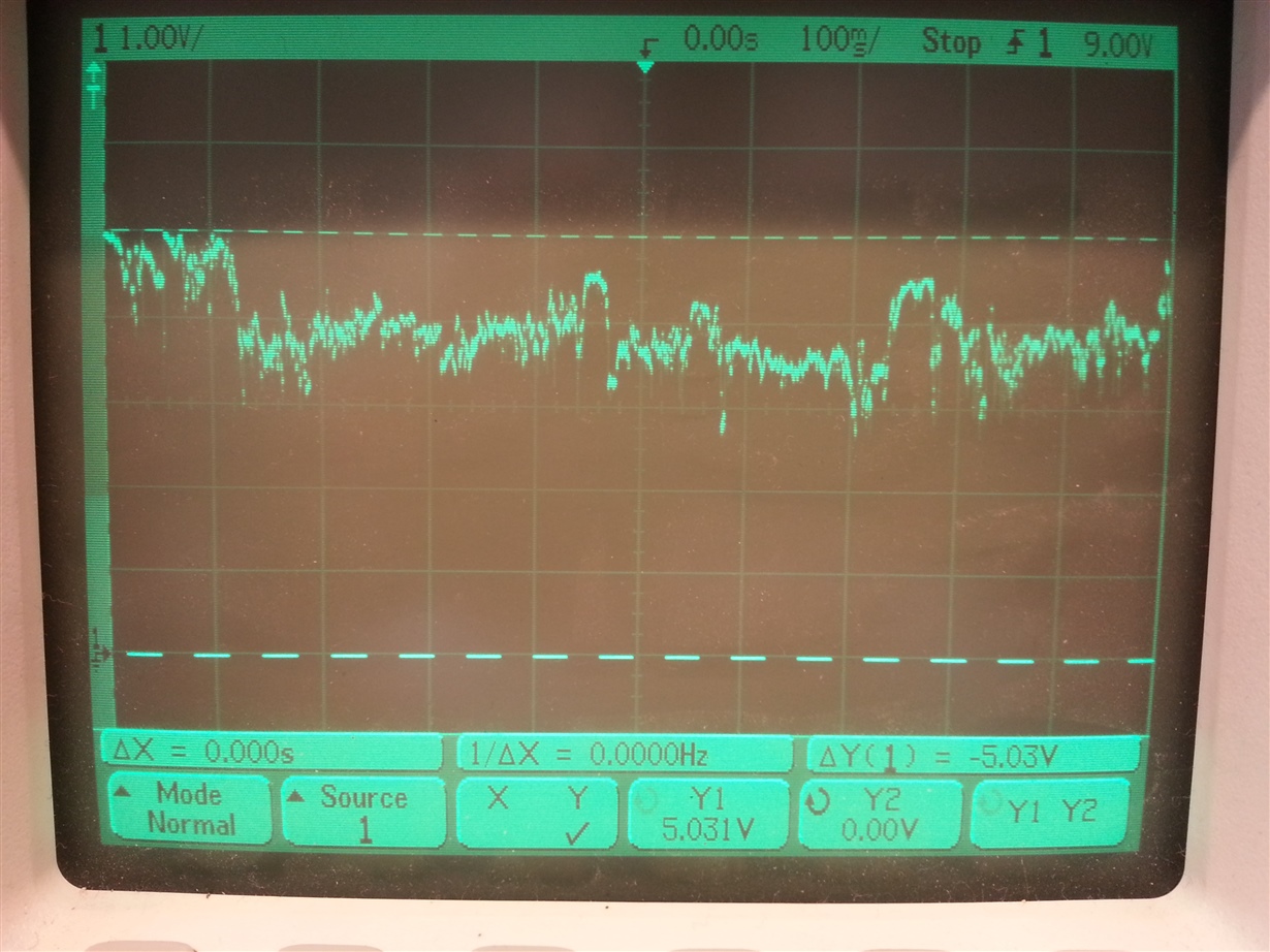
I also see that the 5V output from the DRV8301's buck converter is very unstable. Sometimes it is as low as 3,5V, with a lot of noice. 

Is it possible that the new MOSFET's with the low gate charges causes the DRV8301 to blow up? Or is there something else causing the fault?

Here is the data for the OLD MOSFET's:
Vishay SUM110N06 3m9H - R_ds=3,9ohm, I_d=110A, V_ds=60V, Q_g=200, PWM_max(calculated)=25kHz

Here is the data for the new MOSFET's:
Fairchild Semiconductor - R_ds=3ohm, I_d=120A, V_ds=100V, Q_g=86, PWM_max(calculated)=56kHz

I am a bit tired of replacing the DRV8301 chip now (this will be my 4th time). It has blown up by different reasons. On the positive side, my SMD-soldering-skills is getting better and better... :-)

My project is also discussed in this page: e2e.ti.com/.../1470208

  • Hi Fridell,

    Sorry for the trouble you are experiencing. We will begin investigating the problem on our side.

    Can you confirm the maximum voltage of the 54V battery back? Is it 54 nomimal or fully charged?

    Thanks.
  • Hello Rick

    When fully charged, I have 58.8V, nominal 50.4V. I have not run the motor with regen. braking, so I am pretty sure that the voltage havn't been over 58.8volts.

    Thank you for investigating this!

    Best regards
    B.Fridell
  • Fridell,

    Have you been able to take an o-scope to the outputs and PVDD during operation yet to see if anything unusual is going on? Can you provide scope plots? Since you are running so close to the Abs. Max voltage we need to make sure there are not any unusual transients happening.

    Unfortunately it sounds like the device has been permanantly damaged.

  • Hello Nicholas.

    I don't get to download/debug to the F28069 anymore (Error connecting to the target: (Error -1041 @ 0xFFFFFF66)). Maybe this is because of the unstable 5V? I also see that the LED6-Fault is immidiately lit after applying power to the ev.board. This means that I can not run the motor. 


    Here is a plot of my 5V, measured at J2:

    As you can see, it is very noicy. Sometimes, it drops below 3V, and sometimes is looks normal (5V).

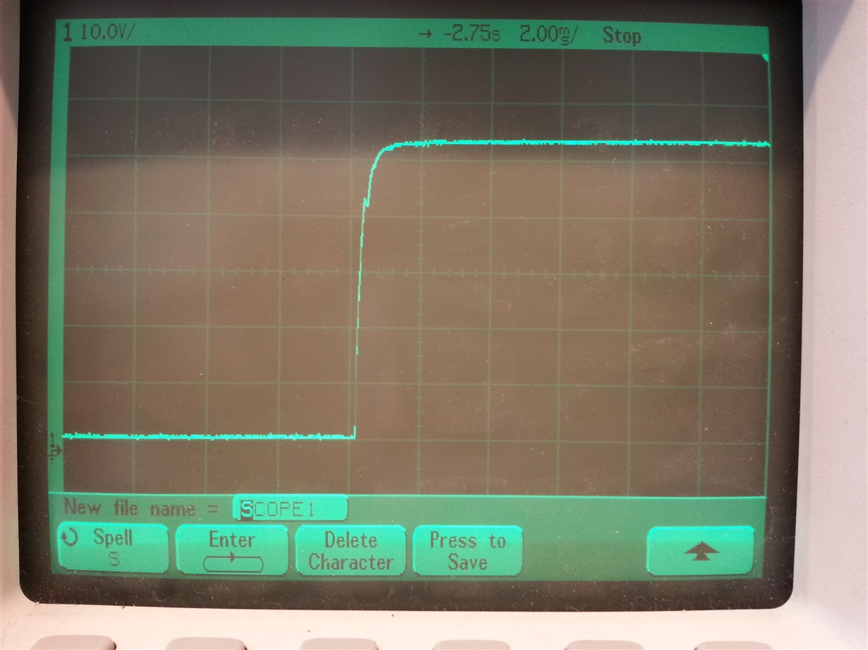
    Here is a plot of the PVDD, immidiately after powering up the board:

    As you can see, the voltage raises up to 53V (not exceeding 60V). 

  • Hi Fridell,

    What is different when connecting the battery pack versus a power supply? We know the voltage, but:
    What is the voltage ramp rate dv/dt?
    When is the voltage provided, on initial contact with the board or through a switch?
    When connecting the battery pack, is there a chance that the voltage is rising and falling quickly several times as contact is made?

    We don't have a 54V battery but may be able to mimic the behavior using a power supply that is already enabled.
  • HI Fridell,

    I am more concerned with voltage spikes during operation of the motor.

    I would recommend replacing the DRV8301 and do some testing with a power supply again. Start at 32V and slow increase the power supply up to 54V. As you are slowly increasing the power supply analyze the PVDD and SHX signals for any voltage transients or spikes.

    If you can run at 54V with a power supply no issues then you can move to the battery to try and debug the root cause of the driver failures.

  • Rick Duncan said:
    Hi Fridell,

    What is different when connecting the battery pack versus a power supply? We know the voltage, but:
    What is the voltage ramp rate dv/dt?
    When is the voltage provided, on initial contact with the board or through a switch?
    When connecting the battery pack, is there a chance that the voltage is rising and falling quickly several times as contact is made?

    We don't have a 54V battery but may be able to mimic the behavior using a power supply that is already enabled.

    Hello Rick.

    The voltage ramp with the battery is pretty high. As you can see in my second o-plot, the voltage raises from 0 to 54V in <1ms, meaning the ramp rate dv/dt will be about 150 000. Is there any maximum rate for this?

    The voltage is provided through a switch, and the voltage does not rise and fall several times. (Please take a look at my second o-plot). 

    I will do some more testing when connecting to my battery.

    Thanks!

  • Hello Nick!

    I will replace the DRV8301 one of the next days, and start with some more testing. I will update you as I make progress.

    Can you guys confirm that it isn't my new MOSFET's that give me trouble?

    Thank you for your replies!
  • HI Fridell,

    There is a spec in the Abs. Max table of the datasheet for max voltage ramp rate.

    I cannot say if the MOSFETs are the root cause or not without seeing some of the switching waveforms.

    In theory, a low Qg will lead to faster switching. Faster switching can cause more inductive flyback on the switch node.

    You may also want to try reducing the DRV8301's gate drive strength to 0.25A setting if not already.

  • Okay, I will try that!

    And what do you say about my noicy 5V (see my o-plot)? It was measured on the user-terminal/screw terminals. I had a lot of noice on my 5V also before the DRV8301 broke down. Is there anything else that can be broken causing an unstable 5V?

    Fridell

  • Nicholas Oborny said:

    HI Fridell,

    There is a spec in the Abs. Max table of the datasheet for max voltage ramp rate.

    I cannot say if the MOSFETs are the root cause or not without seeing some of the switching waveforms.

    In theory, a low Qg will lead to faster switching. Faster switching can cause more inductive flyback on the switch node.

    You may also want to try reducing the DRV8301's gate drive strength to 0.25A setting if not already.

    Hello!

    I have now replaced the DRV8301 chip. Everything is working fine, but something strange happend. The first 5 minutes after connecting to my 30V powersupply, the 5V was very unstable again. Than, suddenly, it went "normal". And now, it have been perfect for many hours. Maybe this is because of some bad connections, I don't know. 

    I have tested a lot with different voltages, and everything seems normal. I have run with up to 58V voltage from power-supplies. 

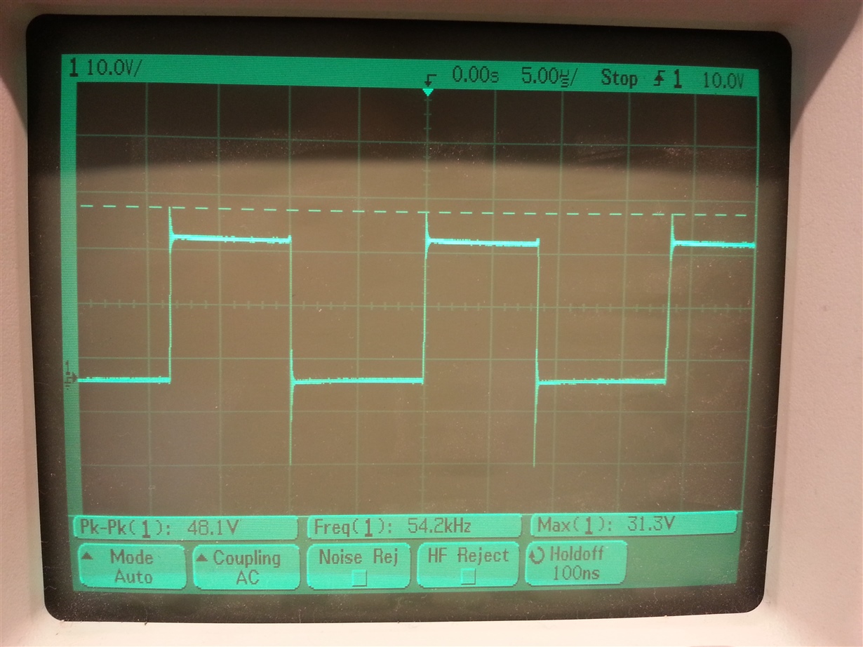
    Here is an o-plot from channel A:

    I have not connected my batteries yet. I want to be shure that connecting doesn't brake the DRV-chip again. 

    Could you guys help me with this? Is there some other parametres or hardware-solution that I can adjust to prevent damage?

  • Hello again.

    I have searched the web, and came across this:

    e2e.ti.com/.../398537

    It seems like lowering the gate-drive strength and maybe insert a series-resistor may fix my problems?

    (I forgot to write in the last post that the o-plot is captured with default gate-drive strength). I will try to lower it and capture a new o-plot.

    Is there anywhere in the code I can change to smaller gate-drive strength, or do I have to change it real-time in CCS?
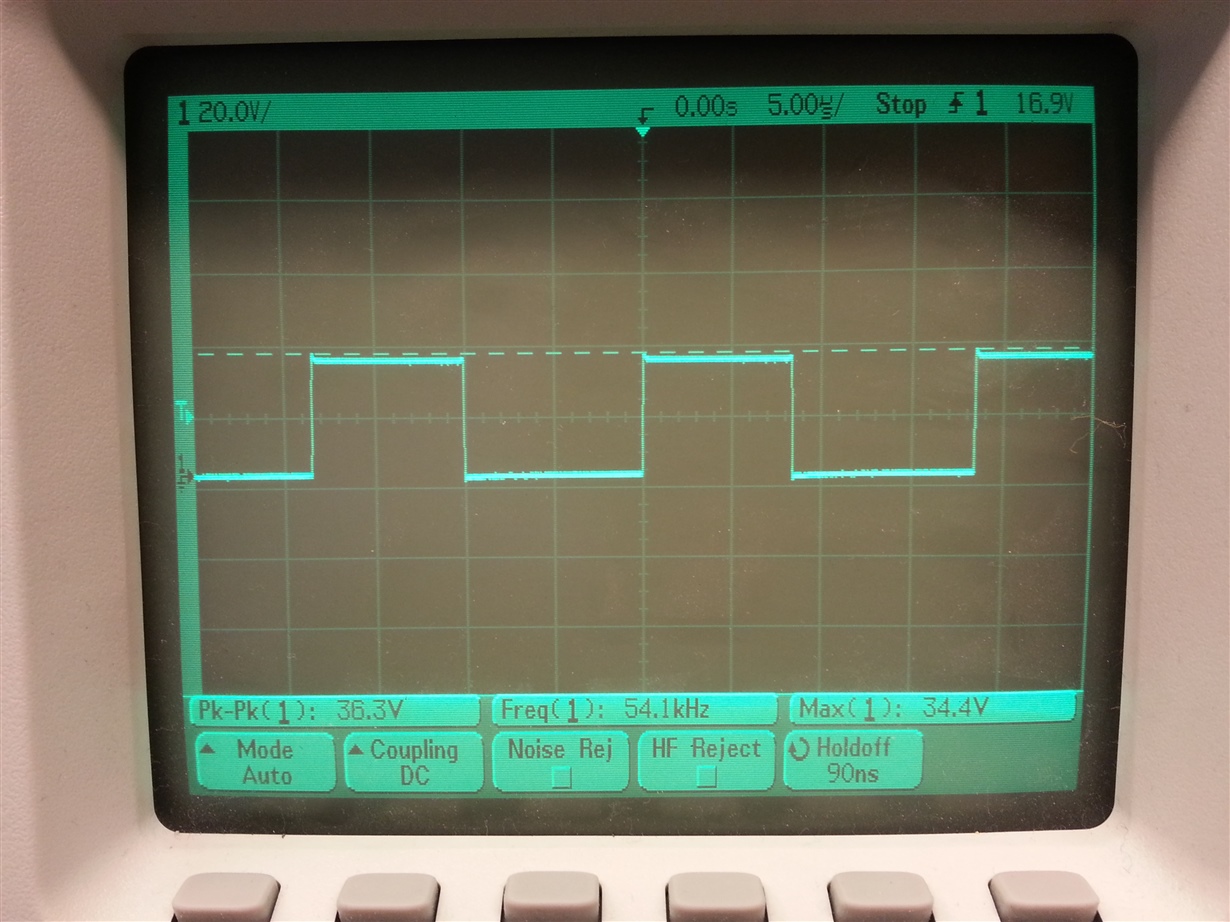
  • I have now changed the gate-drive strength to 0,25. The motor-output now looks a lot better! No voltage-spikes!

    I will now try to connect my battery :-)

  • Good to hear Fridell,

    Yes, for most MOSFET's series resistance will need to be added to prevent ringing on the outputs. I would check the outputs up to your specific battery voltage using a power supply first.

  • Hello again!

    I also changed the gate resistance to 15ohm resistors (default was 1ohm). The ringing is almost gone, even if I run on my batteries.

    I see that the dV/dt on PVDD (when powering up the board), is pretty high: 0,5V/microsec, while the maximum is 1V/microsec. It is pretty close to the limit, so I will try to reduce it with some kind of precharge circuit.

    Thank you for your help!
  • Good to hear and no problem.

    Bulk capacitance on PVDD can also help to limit the voltage ramp rate and prevent any unwanted overshoot.