This thread has been locked.

If you have a related question, please click the "Ask a related question" button in the top right corner. The newly created question will be automatically linked to this question.

DRV 8842 Internal Over Current Protection is Faulting to soon?

Other Parts Discussed in Thread: DRV8842, DRV8842EVM

Hello,

I am attempting to use 4 DRV8842's to drive 2, 24V 5A Stepper Motors. Since I am new to this device I set it up on a breakout board.

Rough Schematic is here:
https://upverter.com/StanTheMan/ba8f34e22c496180/TI-DRV8842-Breakout-Board/
The Sleep, Reset, I0-I4 Pins, Decay, IN1 and IN2 Pins are set as follows:
Sleep - 5VDC
RESET- 5 VDC
I0 - 5VDC
I1 - GND
I2 - 5VDC
I3 - 5VDC
I4 - GND
Decay - 5VDC
IN1 and IN2 are toggled to a PWM Waveform

I set the 3.3 directly to Vref and set the ISEN resistor to .133 Ohms for a 100% current chopping of 5 Amps.

My issue is that anytime I draw more than 1.2 Amps through the device it goes into it's fault mode.
I have the issue across several devices and have confirmed the 1.2 Amps through an oscilloscope
current probe reading and verified it by checking the current drawn from my table top DC Power Supply.

I have ruled out the Under Voltage Lockout as I am supplying at least 14.4 VDC during basic testing.
(I was testing smaller individual DC Motors to see how the drive worked. So I was using 14.4 VDC)

Adjusting the PWM signal's duty cycle and the length of testing have not yet caused the fault to trip.
Also the chip stayed at a nice 29.0 Degree C while I was testing it. With that in mind I can not see how
it could be the Thermal Protection kicking in.

This only leaves me with the Over Current Protection activating at roughly 1.2 Amps.
I can set the PWM to a reasonable setting and vary the duty cycle. However once the chip
sees 1.2 Amps across it, it goes into it's fault mode and I have to reset the chip to continue
testing.

I have this issue across several chips and at this point I am stumped. Is my setup incorrect?
Could I have possibly damaged the chips while soldering them? If so is there a way I could check
for that?

Thank you for your help and time.
-Stanley


  • Hi Stanley,

    Are you looking at the voltage at the VM pins of the DRV8842?

    Also, are you measuring current through the stepper winding or the power supply? These can be completely different. The settings you have shown is attempting to regulate the current at 3A in the winding.

    Based on your schematic and settings, I would suspect that you are entering undervoltage. Overcurrent is unlikely, though it cannot be ruled out.

    I do not see any bulk or local capacitors on VM to maintain the supply voltage locally when the DRV8842 attempts to drive 3A through the motor winding. Lack of bulk and local capacitor is a common problem.

    Please try adding a 100uF bulk capacitor and 0.1uF local cap at each VM pin. For reference, the DRV8842EVM schematics and layout are available online.
  • My baseline was measuring current through the Out 1 line while driving a 24 Ohm Resistor. I will try adding the capacitance to the line.

    -Stanley
  • Hello,

    I am monitoring voltage at the OUT1 pin on the driver. The current is also being monitored there as well. For my current setup I have been testing the current chopping/ limiting with a rotary pot. I added a 470uf capacitor since I did not have any 100uf caps. It helped a lot but did not solve my problems. I hand re-flowed another chip by laying down solder then re-flowed it with a hot air iron. It had similar issues so I baked it as close to the specification as I could then did another re-flow keeping the hot air under 200 C. I added the bulk capacitance of 470uf and it seemed to help but the following problem still occurred.
    The chip's nfault pin would not drive high. I had success with other chips of this type giving me a 5 VDC high and a 0 VDC low without being attached the a pullup resistor. I added a pullup resistor of 10K and connected it between the 3.3VDC supply on the chip to the nfault pin. The nfault pin in now giving me a 3.3 VDC high and a 0 VDC low. Is this pin supposed to have a pullup attached?
    Also last week despite setting the 100% chopping current to 5 amps, the chip decided to 100% chop current at 4.2 amps. The chopping looked fine and similar to what others had posted so I assumed it was correct.
    The over-temp protection kicked on a few times and would reset itself after the chip cooled off. Which I thought the user had to reset by toggling the reset pin. Having these issues and having to travel over the weekend I stopped, disconnected my setup, and stored it in an ESD bag over the weekend.
    I came in today took it out of its bag reconnected it exactly as I had before. However upon powering it up the chip worked well. Chopping took over at 5 Amps or where ever else I set the I0-I4 pins at. The chopping wave form looked very different however. I was able to test the over current protection as I sent 6+ Amps through the chip and the chip faulted. So it seems to be working but the chopping is different. I'll try to have scope captures for you tomorrow.
  • Hi Stanley,

    Glad to hear you have made some progress.

    The chip's nfault pin would not drive high. I had success with other chips of this type giving me a 5 VDC high and a 0 VDC low without being attached the a pullup resistor. I added a pullup resistor of 10K and connected it between the 3.3VDC supply on the chip to the nfault pin. The nfault pin in now giving me a 3.3 VDC high and a 0 VDC low. Is this pin supposed to have a pullup attached? 

    Yes, a pullup should be attached to nFAULT. This is an open drain output. It is possible that there may have been a short to nSLEEP causing you to see a voltage on nFAULT previously.

    The over-temp protection kicked on a few times and would reset itself after the chip cooled off. Which I thought the user had to reset by toggling the reset pin.

    Per page 10 of the datasheet: If the die temperature exceeds safe limits, all FETs in the H-bridge will be disabled and the nFAULT pin will be driven low. Once the die temperature has fallen to a safe level operation will automatically resume.

    Having these issues and having to travel over the weekend I stopped, disconnected my setup, and stored it in an ESD bag over the weekend. 
    I came in today took it out of its bag reconnected it exactly as I had before. However upon powering it up the chip worked well. Chopping took over at 5 Amps or where ever else I set the I0-I4 pins at. The chopping wave form looked very different however. I was able to test the over current protection as I sent 6+ Amps through the chip and the chip faulted. So it seems to be working but the chopping is different. I'll try to have scope captures for you tomorrow.=

    Is it possible that either a piece of solder or some other residue was affecting operation prior to storage and was dislodged when packing/unpacking? 

    We will await your scope captures.

  • Hello,

    After soldering the chips to their boards I checked with a multimeter for shorts across the pins. While I was doing that I also used a magnifying glass
    to check for debris. I did not see either a short or debris.

    Is there anyway to detect what kind of a fault is active?

    I realized it was my mistake for the chopping current. I was sending the drivers too high of a frequency and at lower frequencies it looked much better.

    I was able to run smaller dc motors. Then I was able to put two of the drivers together to run a small stepper motor. I have been attempting to run the 
    actual motor however I am having issues with it. I am trying to get a scope capture however I am not catching the issues. I will be verifying it is not a code
    issue and when I get the scope capture I will post it. Thank you for your help and patience thus far.

    -Stanley

  • Hi Stanley,

    Determining the type of fault is based on the response. Overcurrent creates a need to reset or power cycle the device. Overtemp shuts down the outputs until the device temperature is reduced.

    Will wait for more details and scope captures on the actual motor.
  • Hello,

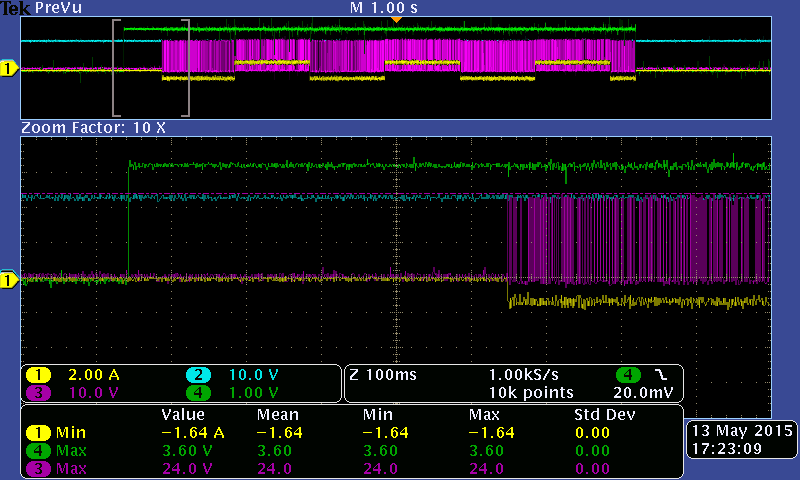
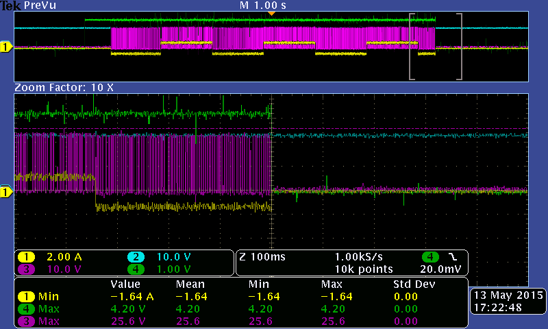
    Using two of the drivers I was able to run a small stepper motor. However while running the larger one, chopping at ~1.6 amps and supplying 24 VDC one of the drivers faults. This is very similar to the issue I was having when driving the DC motors with it.

    Here are two scope captures I took today.

    The first the the beginning of the wave form when I reset the chip. I reset the chip, the fault line goes high and the chip starts to generate the waveform

    to the motor.

    Signal 1 is the current through the motors windings. (OUT1 on the chip)

    Signal 2 is the Voltage at the VM pins.(Should be 24 VDC)

    Signal 3 is the Voltage at (OUT2 on the chip)

    Signal 4 is the voltage at the nFault pin.(Should be 3.3 VDC while not faulted)

    The second capture is of the waveform when the chip faults. There does not appear to be an over current condition or a undervoltage condition. The exterior die temperature is approximately 30 C.

    I have rerun this same wave form and the fault is not consistent. The end waveform when it faults all look similar but do not occur at the same location in the wave.

  • Hi Stanley,

    This could still be an overcurrent event. An overcurrent is defined as anything greater than 6A for more than the OCP time. The datasheet does not state the OCP time but look for anything greater than 2us. If the DRV8842 was still running after nFAULT went low, the fact that the output did not turn back on is an indication of overcurrent.

    Can you set the scope trigger on the falling edge of nFAULT and zoom in to 20us per division?
  • Hello,

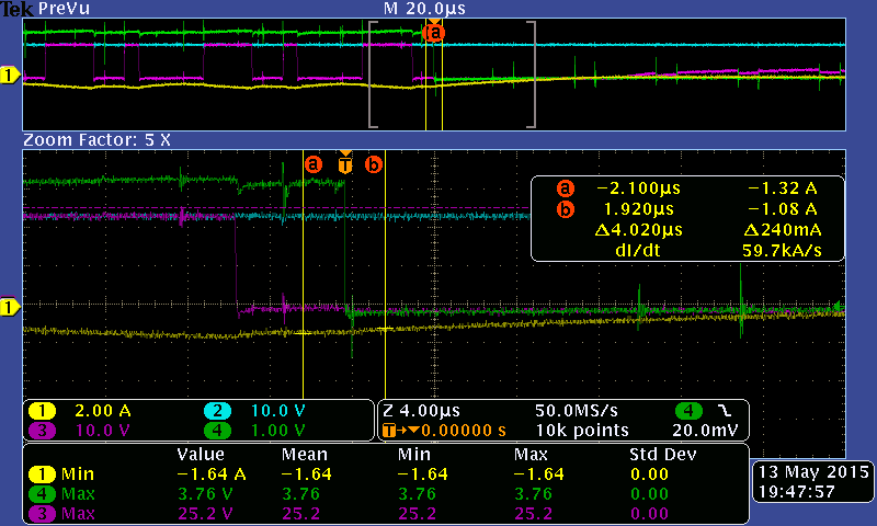
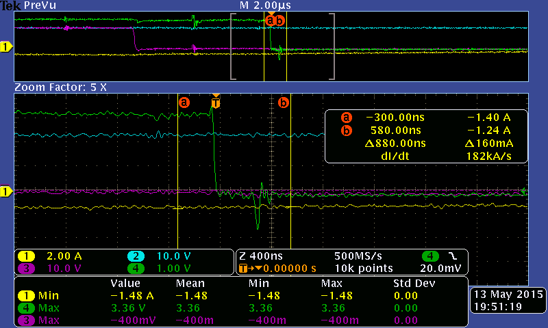
    Here are two more scope captures this one is set with a much higher resolution. The first is the scale at which
    the waveform was captured. The second is the waveform zoomed in 5X. Signals are the same as above.

    Signal 1 is the current through the motors windings. (OUT1 on the chip)
    Signal 2 is the Voltage at the VM pins.(Should be 24 VDC)
    Signal 3 is the Voltage at (OUT2 on the chip)
    Signal 4 is the voltage at the nFault pin.(Should be 3.3 VDC while not faulted)

    4 us per division

    400 ns per division. Zoomed 5X from the 4us per division capture.

    Please let me know if you need another capture or another line to be monitored.

  • Hi Stanley,

    So it doesn't seem to be overcurrent based on this. Undervoltage does not look like a problem either. So the last thing to check is overtemp and firmware. It is unlikely based on the 30C that you reported but please check it anyway.

    What does your firmware do when nFAULT goes low? Does it stop driving completely and disable the outputs?

    Also, what does the connection to the thermal pad look like? Can you provide either a layout or a pdf of the layout?
  • Hello,

    I have verified several times with an IR temperature sensor that the top of the die is around ~30 C.
    I am sendng the commands to the drivers via an Arduino. The Arduino currently is blind to the faults and
    will continue to send commands regardless of the drivers fault status. (In the future I will be adding a
    fault check and reset however for now I am doing bare bone basics.)

    The schematic can be found here upverter.com/.../TI-DRV8842-Breakout-Board
    The thermal pad is connected to the ground trace which is pretty small. I am using a one layer board for preliminary testing.
    I am using another driver as well with the same setup and it is not having this issue. (It is also staying around 30 C for this testing)
    The driver with the issue is one I hand soldered with an iron after using a hot air iron to connect the thermal pad to the ground trace.
  • Hi Stanley,

    Sorry I missed the layout before. Looking at the layout, there are still a few issues.

    Did you add the local 0.1uF caps? The local 0.1 have lower ESR and provide faster response to the current demands. When adding them, please connect the ground to the trace running under the DRV8842 to minimize the loop.

    It is still puzzling why the device stops working with nFAULT set. Have you looked at VM at the pin with respect to the device ground pins?

    You mentioned you are using another driver with the same setup. Is this a second DRV8842? If so, what is different?
  • Hello,

    I did not add the 0.1uF caps. I will look into adding them. I feel it is not a current demand as the fault is not consistent. It is not when it first turns on nor at a consistent location. Furthermore the scope showed that the voltage was at a fine level when the fault occurred.

    Both chips are DRV8842 and are from the same reel.
    The only difference in the chips is how I mounted them to the board.
    The one that is working I:
    Baked per the spec.
    Used a hot air iron to reflow maintaining the temp below 200 C

    The one that isnt working:
    I mounted directly from the moisture resistant package.
    The chip was mounted within the correct time and with the
    correct humidity levels.
    I used a hot air iron to reflow the bottom pad to the board.
    Then I used an iron to solder each of the pins to the board.

    I tried baking and reflowing two more chips the same way
    I did the one that is working. They are not working as well.
    Is there a dead time between mounting and using the chips?


    -Stanley
  • Hi Stanley,

    No, there is no dead time between mounting and using the chips? It is usually a few minutes due to cleanup and setup.

    This is puzzling why one works and the other doesn't. Is it possible to build up another board from scratch?

  • Hello,

    At this point, without the 0.1uF capacitor, I have built 5 separate boards from scratch. The original two that we have been talking about plus three more. All of the other three have issues as well. Two of them will not enable their outputs and the last one will fault if the chopping is above 1 Amp. Each of them have something wrong with them however they are not even consistently wrong. I do not know how to proceed at this point and I am about ready to give up on the drivers.

    I bought enough material to build and play around with roughly 20 boards. If you have any suggestions I am open to them.

    -Stanley

  • Hi Stanley,

    Sorry to hear you are having such trouble. For the two with no outputs, please try with no load and look around the device inputs and outputs. This sounds like there may be bad connections somewhere.

    From the soldering side, please take a look at www.ti.com/.../spraby1.pdf

    If using lead free solder and the temp is less than 217C, it is not liquidous. You can try taking the device up to 260C max per the profile. This may help with the thermal pad connection.

    Is it possible to find someone who has access to a solder rework station that can run the profile? This should create more repeatable results.
  • Hello,

    I will read the document for the soldering side. If I can I will use a reflow machine to mount two more chips. I am
    unsure if the one we have has the right profile.

    for simplicity's sake I will refer to the two boards we were talking about as boards #1 and #2.
    #1. Seems to work fine with no known issues.
    #2. Works but will trip into fault inconsistently. Adding the 0.1 uF caps did not help.

    Boards #3, #4, and #5 I recently built up.
    #3 is not in fault but will not enable its FETs when commanded. Even after toggling the reset pin the FETs can not be commanded.
    #4 is in fault but can not be reset out of fault. Toggling the reset pins will not reset the device.
    Both showed 0.2 VDC after being mounted and a day later showed 0.0 VDC when I checked their OUT pins. No debris or accidental pin connections that I can detect.
    #5 has issues with its chopping. I am using the mixed chopping setting leaving the decay pin not connected. When the current is lower than 4.2 amps it chops correctly. Anything above that and the chip disables its bridges and intermittently enables them. Also when the reset pin is toggled to ground for the reset a short is created through the chip. This shorts out the 5VDC line. There are not shorts to other pins that I can detect and no debris that I can see.
  • Hello,

    Sorry for the delay in response. Just a heads up that I have gotten access to a pick and place machine and a reflow oven that can meet that spec. I will be mounting a few more boards at the end of next week. I will let you know how that goes.

    -Stanley
  • Hello,

    I have not been able to mount any boards using the reflow oven. Due to time constraints I can not spend anymore time troubleshooting these
    parts.

    I hate giving up on these parts because they look like really good parts. Is there something else it could be?
    If I have time later I will try to use the reflow oven to mount another board but if I can it could be months from now.

    Thank you for your help.
    Stanley
  • Hi Stanley,

    Sorry to hear you have to give up for now. This is a good device that works well.

    As we discussed, the lack of local filter caps, bulk caps, trace size and adequate heat sinks can contribute to problems.

    One suggestion for your future debug is to consider purchasing a DRV8842EVM. This will allow you to compare your board with the DRV8842EVM. Good luck next time around.