This thread has been locked.

If you have a related question, please click the "Ask a related question" button in the top right corner. The newly created question will be automatically linked to this question.

DRV8833 shows unstable output

Other Parts Discussed in Thread: DRV8833, DRV8833EVM

Hi,

I'm using DRV8833 to create simple waveform. As you can see in following capture (upper one is output and bottom one is input), it is quite unstable. I want to see one straight line but it keeps fluctuating. I just captured one side but the other side of output shows pretty much same result.

Any comment or feedback would be greatly appreciated.

Regards,

Brian

  • Hi Brian,

    This appears to be due to current regulation, although there is no timescale to confirm it. Please take a look at section 8.3.3 of the datasheet.
    Can you zoom in and provide a timescale on the capture?
    What is the sense resistor value?
    What is the voltage?
    What is the desired current?
    What is the load? (R and L)

    Assuming there is a load, please remove the load. This will disable the current regulation so you can see the desired operation.
    Once you confirm it is current regulation, the sense resistor value may need to be changed.
  • Hi Rick,

    Please look below for zoomed capture.

    I used 200m-Ohm sense resistor. Input voltage is near 3V and output voltage is around 3.7V.

    Actually I don't care about the current but higher is better. The load is very small. I used simple coil to create magnetic field from current.

    How should I deal with sense resistor? I used 1Ohm, 200mOhm, and 100mOhm. 1Ohm and 200mOhm show almost same result and 100mOhm was worst. Can you please tell me what could be most suitable value for sense resistor?

    Thanks,

    Brian

  • Hi Brian,

    Thanks for the zoomed captured. This appears to be the current control circuit operating as designed. When the voltage across the sense resistor reaches 200mV, the outputs are disabled until the next internal PWM cycle.

    When current control is activated, the outputs enter slow decay. Slow decay minimizes current ripple when regulating current. Depending on the inductance of the coil, there may be little change in the current while the outputs are in this mode.

    At 1Ohm, current control occurs at 200mA. At 200mOhm, current control occurs at 1A. At 100mOhm, current control occurs at 2A. Using a 100mOhm resistor may create overtemperature conditions, which would cause the device to disable for longer times.

    To obtain more current, there are a few options available:
    1) You could run the two outputs in parallel as shown in Figure 7
    2) You could potentially disable all current control by connecting xISEN directly to GND.

    In both cases above, care must be taken to avoid overtemperature and overcurrent.

    What is the resistance of the coil and the duty cycle
  • Hi Rick,

    Two outputs were already in parallel from the beginning. Now I made xISEN to the ground and it gets worse. Now I don't recognize which one is high and which one is low. Maybe I should take only one of them, not both?

    Resistance of the coil is about 1.5 ohm. Do you think I need to add another resistor next to coil to reduce the output current?

    Thanks,

    Brian

  • Hi Brian,

    The device should be able to work properly with a coil resistance of 1.5 Ohms at 3V and the output xISEN pins grounded.  << correction

    There are a few items to check in this condition:
    1) Please take a look at VM during this time. If VM is drooping, the outputs will turn off. This can be corrected by adding more capacitance close to the VM pin.
    2) Is the thermal pad of the device soldered down and providing adequate heat dissipation? If not, the device could be entering thermal shutdown.
    3) When reporting the coil resistance, did you zero out the test leads? This can sometimes cause a 1 Ohm difference in readings. If the coil resistance is really .5 Ohms, the device could be entering overcurrent.

    Overtemperature, undervoltage, and overcurrent can be monitored at the nFAULT pin.
    If the outputs are disabled for approximately 1.35ms, it is an overcurrent.
    If the outputs are disabled for different times, it is either undervoltage or overtemp.

    The device is designed to regulate current if a sense resistor is used. Once the current level is reached, both outputs will be driven low to re-circulate the current until the next internal PWM cycle. That is why you see the output toggling high and low.

    If you want a specific current through the coil set the sense resistor to the value based on equation (1) on page 10. The device will then regulate the current with minimum ripple.

    There is no need to add a resistor in series with the coil to reduce the output current. Adding a resistor is a loss of efficiency.

  • Hi RIck,

    VM seems okay. It never drops to low. And I don't think it's problem of thermal pad. Temperature feels okay in DRV8833.

    I captured the two outputs with nFAULT pin. Please look below result. nFAULT never goes up to high and always remained in low. Can you tell me what I need to look to find the reason it stays in low?

    Thanks,

    Brian

  • Hi Brian,

    Can you provide your schematic?
    nFAULT should have a pullup. Does it? Without a pullup resistor to 3V, nFAULT is not valid.
  • Hi Rick,

    It seems that nFAULT pin doesn't give me useful info. Below is what I got when I connected nFAULT to pull up resistor. It just shows little bit of fluctuation but there is no drop point except start and end points.

    One thing I noticed was nFAULT dropped even before input wave starts. Do you think over-current already happened even before input was fully given so that all the waveform messed up after that? Can you please tell me what I could try to fix this?

    Thanks,

    Brian

  • Hi Brian,

    What is happening at the inputs and VM when nFAULT drops? This will provide clues.

    Have you removed the loads to verify proper operation of the device? This should remove overcurrent and overtemp from the faults if the device is operating properly.

    Can you provide a schematic?
  • Hi Rick,

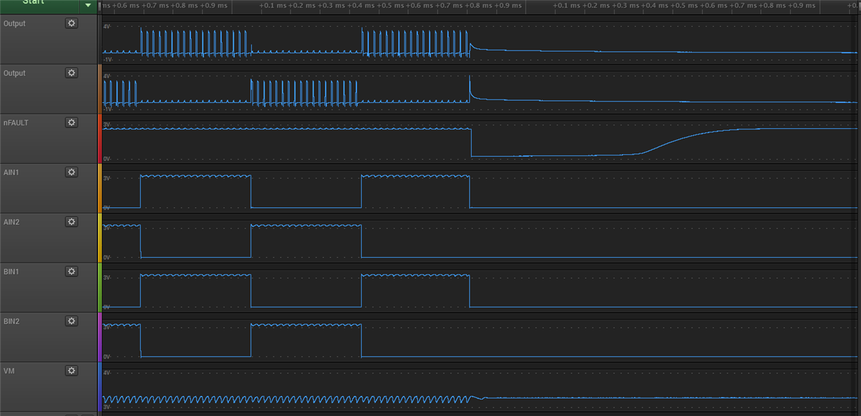
    Please find the full waveform in below.

    As you see, nFAULT drops in the middle of first input period. There is little disturbance in VM but it stays in high. And here is capture when both inputs goes 0.

    I don't quite understand what the captures mean. If you have any clue what's going on, please let me know.

    Thanks,

    Brian

  • Hi Brian,

    For the top image above, the nSLEEP input is not shown. When does it transition to a logic 1? If less than 1ms prior to the inputs toggling, the nFAULT in the middle of the first period may be invalid.

    Please note the tWAKE specification. It is recommended to wait 1ms after wakeup prior to enabling the outputs.

    For the bottom image, did nSLEEP transition to a logic 0 at the same time as the inputs go to 0?

    Would you please provide a schematic of the DRV8833 and the inputs?

    There is a DRV8833EVM available that may be helpful. It can be used to evaluate the device, and the schematic and layout can be used for reference.