This thread has been locked.

If you have a related question, please click the "Ask a related question" button in the top right corner. The newly created question will be automatically linked to this question.

DRV8840: NFault is high but bridge is not actuating

Other Parts Discussed in Thread: DRV8840

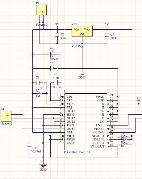
Hello, I have built my own circuit using the DRV8840. The schematic is below. I believe that the 9V supply is in spec (greater than 8.2V) and my logic level of 5V is still ok according to the data sheet. I've checked the solder connections and the wirings several times, so I believe there must be something wrong with my design. When I power up the device, and I set ENABLE to 5V, nothing happens. The voltage levels are all what they should be, but the motor doesn't actuate. 

Note that I'm not using a PWM, I'm driving with DC 5V. 

Any ideas on what the issue might be? Thanks! 

Matt

  • Hi Matthew,

    Would you take a look at the VM voltage at the pins with respect to the GND pins of the device?

    With the configuration you have, the instantaneous current may cause VM to drop below the lockout voltage. This could be repeated each time the voltage rises back above UVLO.

    What is the motor specifications (R, L)? Did you intend to limit the current on startup? If so, you should consider adding a sense resistor and adjusting VREF.

    Please refer to post e2e.ti.com/.../403905 The problem described is due to similar conditions.
  • Thanks for the response, Rick.

    The motor has a resistance of 4.5 ohms. Don't have the inductance information on hand (the motor is hand-wound). I don't intend to limit the current. At just 9 volts, I didn't think I would need to.

    I did include a 100uF capacitor at Vm, which I thought would prevent undervoltage from occurring.

    I will check Vm with a scope tomorrow morning. If this is the issue, what do you recommend as a fix?

    Best,
    Matthew
  • Hi Matthew,

    At 9V, you are correct. You should not need to limit the current. If VM is drooping, adding a 0.1uF capacitor at each VM pin will help.

    Adding the 0.1uF provides the initial current that the bulk cannot.
  • Hello Rick,

    It doesn't seem like this is the issue. I triggered a scope with enable and looked at OUT1, OUT2, and VM. Nothing seems to imply that the IC is doing anything. On enable, VM remains at 9V, OUT1 and OUT2 stay low. I added the extra capacitors just for the sake of thoroughness, and it still doesn't work. I also increased the supply voltage to 12V just to give a higher margin from the lower bound. Same result.

    I've checked the other connections. NSLEEP, NFAULT, and NRESET are all high. I0-I4 are all high. I've tried resetting the board. I've checked the solder connections several times. No shorts and no floating pins.

    I figured there must be something wrong with the IC. So I swapped it out with another one. Same issue.

    I'm really at a loss on what to try next. Any ideas?

    Best,
    Matt
  • Hi Matt,

    Thank you for your diligence checking the board.

    There are a few other items to check before the layout is examined more closely.

    First, please take a look at VCP when the device is enabled. It should be about 10V higher than VM. Also please confirm C9 is a ceramic cap.

    If you are using a power supply, please report the current reading when VM is 6V and 12V. This can provide a clue.

    Since you have checked all the inputs at the pins, this is puzzling.

    Do you have a second board to try? Can you provide the layout?