This thread has been locked.

If you have a related question, please click the "Ask a related question" button in the top right corner. The newly created question will be automatically linked to this question.

DRV8825 Holding Current

Other Parts Discussed in Thread: DRV8825, DRV8825EVM

Hello,

I am using a DRV8825 in my application.  Most of the time it works correctly, but occasionally it will loose holding current (at the end of a move).  I've scoped the enable line, and it remains low.  My application is 'paused' so the is no code executing.  I am able to move the motor freely.  However, if I provide a short, sharp external force (back EMF?), holding current will resume.

In my design, nSleep, and nEnable are tied high to 3.3V, and I do not see nFault trigger.

Thoughts?

  • Hi Luke,

    The first part (able to move the motor freely could be explained if the motor is stopped such that 0 current is running through one winding and the other winding is not connected. The motor may still move under this situation but not optimally.

    Could the short sharp external force cause the second winding to re-connect?

    To confirm, please take a look at the outputs when this event happens. Look for one output pair to be off (high impedance). You can verify this by placing a 1/2 VM resistor divider at one output and measuring the voltage at both outputs. The other output pair may have one output at VM and the other at GND. Once you identify the output that is active, also take a look at the ISENx connection for that output.
  • Thanks Rick,

    Can you please elaborate on what you mean by 'other winding is not connected'? Do you mean internally to the chip, or externally to the system?

    If, by your test, I can identify the active / inactive state of the driver, what would you suggest next steps be and how would ISENx play a role?

    thanks
  • Hi Luke,

    I am speculating that an external connection from the device to the motor is not correct.

    It may be easier to determine what you find, then provide next steps. Can you capture scope shots of the outputs when the motor condition occurs?
  • Hi Rick,

    Here are the respective A+/A- and B+/B- waveforms after a failure with no holding current.

  • Hi Luke,

    Thanks for the scope captures. These show what appears to be both windings driving and regulating current very quickly. So the device is awake and attempting to regulate current. Fast or mixed decay appears to be used, and in both cases the outputs appear to be approaching zero current.

    This is confusing because the indexer table does not have this condition. One winding should be regulating at maximum current when the other is regulating at or near zero current.

    I assumed earlier this is not a TI EVM. Is that assumption correct?
    What are your motor parameters (R/L/V)?
    What are your decay and microstep settings?
    What is AVREF and BVREF?
    What is your sense resistor value?
    Do you have a current probe? If so can you capture scope shots of the current when this event occurs?
    Please look at both xISEN pins with the scope also. These pins should be transitioning between +0.8 and -0.8V. Are they?

    As an FYI, you can look at the TI DRV8825EVM for schematic and layout.
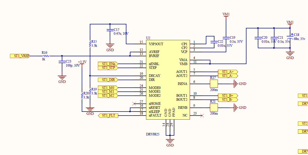
  • Yes, you are correct, this is a home grown board based from the EVM.  Below is a snippet of the schematic.

    Decay mode is mixed, steps are 8 microsteps/step.  AVREF and BVREF are derived from a filtered, PWM signal and ~2.1 V DC.  Sense resistors are 200 mOhm. I will try and get a measurement from the sense pins for you.

    Here is a link to the motor being driven.  

    R = 2.6 Ohm/Phase, V = 3.9 V, L = 4.9 mH/Phase

  • Hi Rick,

    Any thoughts on what may be happening? I'm still very puzzled why 'jolting' the system will cause holding current to resume.

    thanks,
    luke
  • Hi Luke,

    I agree that "jolting" the system to resume the current is puzzling. This scenario has not been previously reported.

    If I had to guess, I would first look for possible cold solder joints at the sense resistors. This could cause intermittent behavior, especially when holding. The second place to look for cold solder joints is the connection to the motor.

    Do you have a second board or motor to rule out possible causes?

    Have you been able to get a scope capture of the sense resistors (both when working and when not)?
  • Hi Rick,

    Here are some scope readings.  The first is either side of the charge pump capacitor, the second are the A and B sense resistors under normal holding conditions, and the third are the sense resistors with no holding.

    Some information during the fail condition, 

    AVREF / BVREF are normal

    nFault = 3.3V

    nReset / nSleep = 3.3V

    nEnable = 0V

    VMA / VMB = 24V


  • Hi Luke,

    Thank you for the scope captures. The first shows the charge pump is active, indicating the device is operating as expected.

    The second and third images are questionable. Both show the sense A resistor (assuming sense A is channel 1) rising to 24V. This should not be possible as it violates the absolute maximum rating. Would you please double check these captures, and the entire path from the DRV8825 pins through the motor and back through the sense resistor?

    In the third image, sense B appears to be at 0 current. This would mean that winding A should be at +/-100% (2.1A based on 2.1V VREF and .2Ohm sense resistor). If you have no holding torque, the current in winding A does not appear to be present.

    I will look at this on our EVM, but don't expect to see the voltage this high.