This thread has been locked.

If you have a related question, please click the "Ask a related question" button in the top right corner. The newly created question will be automatically linked to this question.

DRV8842 Current Sense

Other Parts Discussed in Thread: DRV8801, DRV8842, DRV8312, DRV8701, OPA335

Hello,

is there any way to measure the current beeing delivered by the DRV8842 driver to a DC Motor? I have VFREF connected to V3P3OUT with a 47uF filter Capacitor to ground, and use a 0.13ohm sense resistor to allow a maximum current of 5.08A. I know the DRV8801 has a Vprop output, but I need more power, but also need to measure the delivered current. The used microcontroller has an 0-5V ADC, 100Mohm input resistance.

Thank you, 

Igor

  • Hi Igor,

    Yes, there are several methods. The most common is using an external current sense amplifier (CSA) across the sense resistor. The output of the CSA is then fed into the ADC. As an example, refer to page 16 of the DRV8312 datasheet. This is for a 3 phase motor, but the concept is similar.

    Another option may be to use the DRV8701. The DRV8701 has a built in current sense amplifier, but requires external FETs. The FETs can be sized according to your needs.
  • Hi Rick,

    I have not found any information about the current sense amplifier in the datasheet of the DRV8312 (www.ti.com/.../drv8312.pdf) on page 16.
    Can you please tell me the formula for the voltage over sense resistor ? µC has a 10bit ADC, so resolution would be good if I have .8V at sense while driving 5A of current, but I dont know if this is true..
    Another question, is the current on sense directly proportional to the motor current?

    Thank you very much,

    Igor
  • Hi Igor,

    Sorry for the typo. It is page 26 (Figure 16) of the DRV8312 datasheet.

    You will notice that the current sense amplifier has an offset, which allows both negative and positive current to be measured. If using brake mode (slow decay) to chop the current, this is not important. If reversing the outputs (fast decay), this can be used to stop the flow of current prior to the current reversing.

    The current is proportional to the sense resistor in most cases. The typical exception is a capacitor across the motor windings can cause momentarily large currents.
  • Hi Rick,

    can you tell me the formula for the current flow through sense depending of the motor current? Is the current motor direction-dependent (different sign if cw or ccw motor rotation)? I'm thinking if I can omit the opamp and measure the voltage directly...
    Thank you,

    Igor
  • Hi Igor,

    The current direction is the same through the sense resistor when driving. Please refer to Figure 2 of the DRV8842 datasheet.

    When driving, the current flows from VM through a high side FET, the motor, a low side FET, and the sense resistor to GND.

    When in fast decay, the current through the sense resistor is reversed.

    When in slow decay, the current flows through the low side FETs only.

    The formula is V(CURRENT SENSE AMPLIFIER OUTPUT) =V(OFFSET_CSA) +/- (I*RSENSE * gain of CSA)

    If using an offset of the current sense amplifier, zero current through the sense resistor (outputs disabled) should be close to the offset value. 

  • Perfect Rick!! Thank you very much for your great support!!!

    It was not clear to me, that the sense resistor is between the H bridge low side and ground, and therefore has to support high currents... Thank you very much, I will correct my schematic. A little suggestion: for better comprehension, I'd put a label for the resistor in DRV8842 datasheet Fig. 2 - maybe saves inconvenients to others :)

    Thanks again and have a nice week,

    Igor
  • Hi Rick!!

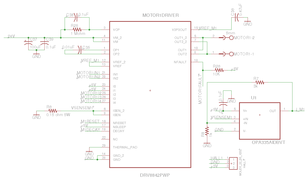
    Happiness!! It's me again. I adapted the circuit to use a OPA335 as Current Sense Amplifier, with a gain of 4 and a 0.15ohm 5W sense resistor.

    With this, I expect that at 3.5A Motor current, the sense resistor drops 0.525V. After the amplifier, at I_M1 I expect to measure 2.1V in this case. Is it correct that I should not use fast decay mode, so I don't get a reverse polarity over the sense resistor?

    Do you see any errors in the schematic?

    Thank you very much,

    Igor