This thread has been locked.

If you have a related question, please click the "Ask a related question" button in the top right corner. The newly created question will be automatically linked to this question.

Temperature of the stepper motor

Other Parts Discussed in Thread: DRV8711, DRV8711EVM

Hello

I use drv8711 for driving stepper motor , when i use recommended initial setting in SLVA632 document (Table 2) , after 10 or 15 minutes , motor temperature will increase , and motor is very hot .

what should i do ?

my stepper motor features :

4.7v , 1.5A , 1.8degree , r = 3.1 ohm , l = 6.1mH

thanks a lot

  • Hi Mohammadmehdi,

    What values are you using for ISGAIN and RSENSE? If you run at a lower TORQUE(TQ) setting less current will be dissipated as heat in the motor windings. Did you calculate the proper TORQUE(TQ) value based on Equation 1 in SLVA632?

  • Hi Phil Beard,

    1) ISGAIN = 5 , RSENSE = 0.1 Ohm 10W

    2) What's the difference between IFS and IOCP ? Is IFS the current that described in motor's features ? and We have IL(Motor Current) in table1(#8) , please explain about it , and what's difference between these 3 item ?

    3) My TORQUE(TQ) value is 0x69

    4) Excuse me , I didn't understand this sentence "If you run at a lower TORQUE(TQ) setting less current will be dissipated as heat in the motor winding" , please explain more.

    thanks a lot
  • Hi Phil Beard

    I'm Waiting For Your Reply.....

    Thank a lot !
  • Hi Mohammadmehdi,

    Sorry for the delay.

    IFS is the full scale current you'd like to operate the motor at. IOCP Is the the Over Current Protection level where the driver will shutdown if this current level is reached. IL(Motor Current) in table 1(#8) is an example of rated current for each motor phase.

    Selecting an IFS (full scale) current below IOCP and the rated current of the motor you're using will allow for safe operation. If the motor you're trying to control is rated at 1.5-A and your selected IFS (Full scale) current is 1.5-A, that will contribute to your motor getting hot.

    Try selecting an IFS (full scale) current of 1-A. Your TORQUE(TQ) value would then be 0x46. The motor should be cooler than it was with an IFS (full scale) current of 1.5-A.

    You can roughly approximate the power dissipated in your motor using P=(IFS^2) * R. For 1.5-A, the power dissipation is approximately 6.975 Watts, but at 1-A the power dissipation is 3.1 Watts. The lower the power dissipation the cooler the motor.
  • Hi Phil,

    Thanks for your reply, a nice answer

    My problem is solved, the motor runs smooth and cool.
    another question....

    1) I want to see current in different Microstepping, Where should I place my oscilloscope probes in my circuit to see that ?

    thanks a lot
  • Hi Mohammadmehdi,

    Typically these best way to see the microstepping current is to use a current probe connected to one of the phases of the motor.

    You can calculate the different microstepping current levels by using the ICHOP equation in section 7.3.2 of the DRV8711 datasheet and then multiplying that value by the percentage of full-scale current found in Table 4 for each microstepping level.
  • Hi Phil,

    I changed my motor for high current test , new motor feature : 2 phase , 1.8 degree , 4.4 A , 0.81 Ohm

    when I connected the motor to my driver with these values ( ISGAIN = 10 , Torque = 0xF1 ) , current value was 0.88 A , and when I increase Torque value and decrease ISGAIN for high current operation , FAULTn Pin pulled Low and DRV8711 disabled .

    my motor worked until 1.2 A , but upper this value wasn't worked .

    what should I do ? Should I change register parameters ?

    Thanks a lot
  • Hi Mohammadmehdi,

    Can you read the STATUS register? This will tell you which fault in the device has been flagged.

    What is the current you're supplying to the motor when this happens? What value are you using for OCPTH?
  • Hi Phil,

    1 ) yes, I can read it , Status value is = 0x59 in both test ( motor worked and motor didn't work )

    2 ) current value is 0.03 A , OCPTH = 11 (1000 mV)

    Thanks a lot
  • Hi Mohammadmehdi,

    Thank you for the information.

    The Status value you provided would indicate the driver has overheated and both predrivers have flagged faults.

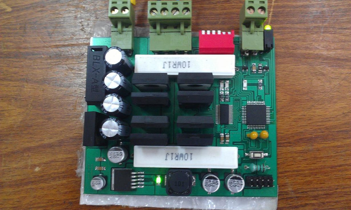
    What is the RDS(ON) and Qg of the external MOSFETs you're using? Can you provide a picture of the board layout you're using?
  • Hi Phil ,

    RDS(ON) = 0.085 Ohm , Qg = 140 nC

    Yes , Board layout

  • Hi Mohammadmehdi,

    Thank you for the picture.

    Could you provide a screenshot of this boards PCB layout from the software used to design it? I'd like to see the ground plane underneath the driver.
  • Hi Phil,

    Excuse me for my long delay

    top layer

    and bottom layer

    thanks for your response.

  • Hi Mohammadmehdi,

    Thank you for the screen captures.  If you look at the ground pour underneath the DRV8711 the path for heat to escape from the package into the ground plane is constricted.  This will cause the die to heat up and eventually flag an over temperature fault.  To solve this problem you need to layout the driver in a way that includes a wide path from thermal pad beneath the driver through to a large ground plane.  

    The Bottom and Top layers of the DRV8711 EVM are attached below, I would advise trying to 

    DRV8711EVM Top Layer

    DRV8711EVM Bottom Layer

  • Hi Phil,

    Thank you for your good support

    I know the ground pour underneath the drv8711 is not good for cooling, but as i experienced with my other Step motor(2.5 Amp), the current increase up to 2.5 Amp with out any problem. however for this new motor (4Amp) i installed a small heat-sink on top of the Drv8711 to provide a good working condition but what is happen confuse me. when i limit the current up to 1 Amp, everything work correct. but when i decrease current limitation to 1.2 Amp or higher the drv8711 stop the driver and error led turn on. Hence i do not think the heat cause this error, i really dont know!

    on the other hand another thing that i guess cause this problem, is the type of the MOSFET that  i used. I use IRFP064N, [55V, 110 Amp,RDS(on) = 0.008ohm]. what do you think about?

    Thank you for all your assistance

  • Hi Mohammadmehdi,

    The problem with installing a heat sink on top of the DRV8711 is the thermal resistance from the silicon die to the case top is high compared to the thermal resistance between the silicon die and bottom thermal pad. This means that heat isn't efficiently removed through the case top compared to the bottom ground pour.

    The difference you're seeing between the 2.5-A rated stepper and the 4-A rated stepper could be due to the difference in inductance between the two motors.

    For the 4-A motor the inductance most likely is significantly less than the 2.5-A motor. The driver must turn on the MOSFETs more often to keep the current at each regulated step in the lower inductance motor because current can change much faster. This causes the driver to heat up faster even if the threshold is set at a lower current value than the higher inductance motor because it's working harder to keep the current regulated at each step.

    Do you have a thermal camera / themocouple to measure the DRV8711 case temperature during your testing? You can measure the device temperature and determine if the fault reported is correct.