This thread has been locked.

If you have a related question, please click the "Ask a related question" button in the top right corner. The newly created question will be automatically linked to this question.

PWM Polarity Inverting Circuit for TEC module using DRV8432 in parallel full bridge mode

Hello,

I am working on a PWM polarity inverting circuit for TEC module with 24V power supply, 1 TEC requires 12A driving current in total. so I am using DRV8432 in Parallel full bridge mode with my design and PWM operatable. I am trying to swap the polarity for heating and cooling. I am just sending a digital input for direction control to a microcontroller board. uC generates the PWM based upon the direction.

If it is in logic high - TEC heating

PWMA - 95% of dutycycle with 40Khz frequency
PWMB - 1% of duty cycle with negative logic

If it is in logic low - TEC cooling

PWMB - 95% of dutycycle
PWMA - 1% of duty cycle with negative logic

the board is working fine if i swap the direction  pin slowly.

If i increase the rate of changing the direction. It triggers the *FAULT and *OTW.  It is showing the output 0.66V.
Any shoot through is happening or something else. Ringing is also there on output at inductors.
Using the Boot strap capacitors  of value 200nF.

Any suggestions would be appreciated!

  • Hi,

    The FAULT and OTW signals are indicating the DRV8432 has detected a problem of some sort. It indicates overtemperature plus either overcurrent or undervoltage.

    Have you examined the VDD and GVDDx pins to determine if the fault is undervoltage or overcurrent?

    How are you increasing the rate of change of direction?

    FYI -- I plan to remove your duplicate post in another thread. Please post only once.
  • Hi Rick,

    Thanks for the prompt reply.

    I am switching the direction pin from logic high to low and low to high for heating and cooling using a logical switch.

    I am just sending a switch output for direction control to a microcontroller board. uC generates the PWM based upon the direction.

    If the direction switches frequently (very fast) then DRV8432 triggers *Fault and *OTW problem.

    I have monitored VDD = 11.86 V.


    Thanks
    Sai
  • Hi Sai,

    Are you monitoring VDD with a scope or a DMM? It is important to use a scope and use the nFAULT and nOTW signals to capture the details of the event.

    Looking at the outputs with respect to the inputs can help determine if the fault is overtemperature. If overtemperature, the outputs will not respond to the inputs until the device cools down. This is can be tens to hundreds of milliseconds.
  • Hi Duncan,

    DRV8432 is in PFB mode to drive a TEC upto 12A @ 24V.

    Used the 24kohm resistor as OC_adj. It is referring Table:2 in datasheet the maximum current before overcurrent occurs is 10.7A.

    Could you please explain what this 10.7A exactly. Whether on each channel is the max limiting current is 5.4A or 10.7A.

    Referring to the link e2e.ti.com/.../133322

    "As Paralleling the outputs are not directly tied together. A ferrite bead or inductor should be placed between each parallel connected output"

    I am using Fixed inductor 4.7UH 13.5A 11.2 MOHM SMD (part no: ASPI-1367-4R7M-T). The inductor current rating is a power ferrite bead can be used instead of an inductor. The current rating is higher than the RMS current of the my system.

    I am getting a nFault error for 6A current @ 15V only. Now DRV8432 is also died.


    Thanks
    Regards
    sai
  • Hi,

    Sorry for the incomplete thread.

    It showed a nFAULT for 6A current @ 15V for a few seconds. It means it is showing Overcurrent at 6A( OC_adj = 24Kohm - 10.7A) itself why it is malfunctioning. Any other thing missing.

    Now If I try to drive it with (PVDD) 10V or other , DRV8432 is becoming too hot and no voltage(showing 0V) at the output though there are inputs(PWMs, GVDD, PVDD..Everything is there). nFault, nOtw are also at high pulse.

    Whether DRV8432 is died or if it works fine then why doesn't it produce outputs for inputs.

    Any help will be appreciated!

    Thanks
    Sai
  • Hi,

    Any suggestions will be appreciated.

    My work is on hold. I am awaiting for the reply. I am planning to buy a few more DRV8432DKD ICs.

    Please suggest me any alternative way.

    Regards

    sai

  • Hi Sai,

    I missed the use of 200nF bootstrap caps earlier. Have you added the 5 Ohm series resistor as recommended in the second paragraph of section 7.3.2.1 of the datasheet?

    If you are PWM'ing at a higher frequency (>10kHz), can you try lowering the bootstrap capacitor to 100nF?

    Are PVDD, GVDD, and VDD pins at the same voltage?

    If so, are you adhering to the recommendations of section 8.2.1.2.2 of the datasheet. The GVDD and VDD pins have a tighter tolerance than PVDD.

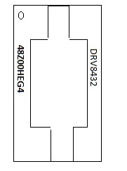
    What are the device markings of the device that is no longer working.

  • Hi Rick,

    Thanks for the reply.

    I am PWM'ing at 40khz a higher frequency (>10kHz), this is the reason 200nF bootstrap caps are added. For this now I am trying to add 5ohm series resistor to GVDD with suggestion.

    Now I think there is no need of  lowering the bootstrap capacitor to 100nF. right?

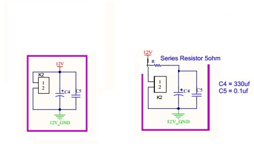
    Here I am just trying to add a resistor of 5ohm in series to GVDD (12V) and GVDD_X. Please correct If I am wrong. Is this the right way of adding resistor. Suggest how much will be the wattage of resistor.

    Yes. I am following the recommendations of section 8.2.1.2.2 of the datasheet for 12V power supply.

    I bought the DRV8432DKD device from Digikey.  Partno: 296-27410-5-ND .

    Look forward to hearing from you soon.

    Regards,

    Sai.

  • Hi Sai.,

    There may have been a misunderstanding regarding the bootstrap cap value. From the datasheet:

    For applications with lower than 10-kHz switching frequency and not to trigger BST_UVP protection, a larger bootstrap capacitor can be used (for example, 1-μF capacitor for 800-Hz operation). When using a bootstrap cap larger than 220 nF, it is recommended to add 5-Ω resistors between 12-V GVDD power supply and GVDD_X pins to limit the inrush current on the internal bootstrap circuitry.

    The larger 200nF is sometimes required when the PWM frequencies is less than 10kHz.

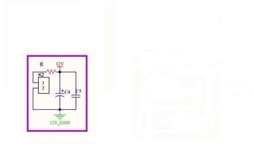
    If you want to add the series resistor, it should be placed between the GVDD_X pins and the source of the current. See modified image below:


    Assuming K2-1 is the 4 GVDD_X pins, the preferred approach is to place the resistor between the GVDD_X and the power supply/bulk capacitor. This could be more difficult than reducing the three bootstrap caps to 100nF.

    At 40kHz, 100nF bootstrap capacitance is sufficient.