This thread has been locked.

If you have a related question, please click the "Ask a related question" button in the top right corner. The newly created question will be automatically linked to this question.

DRV8301, working well at first, then go to fault: GVDD_UV

Other Parts Discussed in Thread: DRV8301, BOOSTXL-DRV8301

Hello

I made a board as DRV8301 kit.

My DRV8301 board can output PWM signals when the chip of DRV8301 is paded, but then begin to fault, the status register said : GVDD_UV.
I change the DRV8301 with a new chip, it working well at the first time, but then it go to fault : GVDD_UV. Why?

My DRV8301 board has the same problems as follows: 
EN_GATE=1; EN_GATE=0
GVDD: 1.33V 0V
DVDD: 3.3 V 0V
AVDD: 6.6 V 0V
PVDD: 16 V 16V

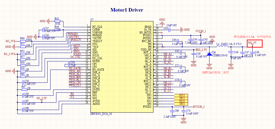
My schmatic is as follows:

  • Hi,

    GVDD should be approximately 11V, which is probably causing the GVDD_UV fault.

    How long did the system work before the fault?
    How fast are you switching the outputs?
    What is the average gate drive current per equation 3 of the datasheet?
  • Hi,

    A few more questions:

    What is the bulk capacitor value for V60_1?
    What is the voltage rating of capacitor C56 (the charge pump capacitor)?
    Can you change C69 to the 4.7uF per the datasheet recommendation?
  • Hello, I see you responded to my post regarding a similar issue.  How heavily are you loaded the motor drive system? Under no load conditions the controller I made worked; however, transient voltages from back emf (under heavy load) caused the chip to fail.  I recommend using Transient Voltage Suppression (TVS) diodes to protect the DRV chip as well as increasing the size of the capacitors on the PVDD line.  I have also talked to similar universities who have increased the size of the charge pump capacitor and that also seemed to help the issue.

  • I test the DRV8301 board under no load conditions.
    It can output PWM signal only a few minutes, and then go to fault. It can not work again.
    The max output PWM frequency is 20KHz.
    The max current is only 50mA on 24V.
  • pin54 and 53, the capacitor for VCC60_1 is 2.2uf/100V (1206 package) and 0.1uf/100V (Monolithic capacitor).
    C56 is 22nF, packege is 0805. I do not know it's voltage rating.
    I have changed C69 to 10uF/63 capacitor, but the problem is still exist.

  • Hi user1416086,

    What bulk capacitor value is used for VCC60_1? In addition to increasing C69, you may need several hundred uF on VCC60_1.
  • I had added a 470uF/63V capacitor on the VCC60_1 line. But it did not solve this problem.
  • Hi user1416086,

    Have you replaced the DRV8301?
  • I have replace the DRV8301 twice. It work well( can output PWM signal under unload condition) first and then go to fault( GVDD_UV).
    I replace the VCC60 bulk capacitor to 10uf/100V on C69 and C41, and add a 470uF/63V capacitor on VCC60 input line, but it can not solve the problems.
    Your means is that my DRV8301 chip is damaged?
    It is the VCC60 bulk capacitor value to low that lead to the fault GVDD_UV and the chip damage?
    OK, I will replace it for a new one tomorrow.
  • The device in your original post with GVDD = 1.33V is probably damaged. If you have not changed it since then, please change it.

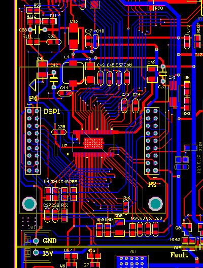
    Can you provide the layout also?
    Do you have any traces under the device that could cause problems?
  • I have changed it with a new one. But the problems still exist.

    " GVDD should be approximately 11V".  Is this status exist on the default situation without DSP config? 

    The following is my pcb. The left is without GND polygon, the right is the final one.

  • Hi user1416086,

    Thank you for the layout. It appears your troubles may be associated with the layout.This layout shows long ground loops for the regulator capacitors and a single metal trace connecting the ground pad of the device. Is that correct?

    It is suggested to follow the layout guidelines described in section 10 of the datasheet. You can also refer to the BOOSTXL-DRV8301 layout as a reference.

    " GVDD should be approximately 11V".  Is this status exist on the default situation without DSP config? 

    No, GVDD should be approximately 11V when the device is powered and EN_GATE = 1

  • Thanks for your reply.

    It may be the PCB layout which lead this problems. I have lead a thick wire from the bottom of the powerpad holes  to the GND, but it can not solve this problems.

    My be , I have to make a new pcb layout instead.

  • Hi Rick Duncan,
    Can I design my pcb accordiing to BOOSTXL-DRV8301 board in addtion to its voltage?
    My board will work on 48V voltage.

    Any other questions I have to pay attention? 

  • Hi user1416086,

    Yes you can design your pcb according to the BOOSTXL-DRV8301. The components (FETs and capacitors) should be changed for 48V operation.
    Depending on the current, the capacitors may need to be increased. The PCB traces and connectors may also require changing if the current is higher.

  • Hi Rick.

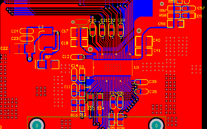
    I have made a new PCB board following to the BOOSTXL-DRV8301. 

    But, it still can not dirvier the motor, The fault code is : GVDD_UV.

    The pin of GVDD is 11V when the EN_GATE is enabled, and then it follow to about 3.7V,

    It changed from 11V -3.7V for several times. 

    I have try to add  a electric capacitor of 10uf or 330uf beside to the pin of PVDD1 and PVDD2 , but it can not change anything.

    the following is my pcb layout:

  • Hi user1416086,

    Something may be overloading GVDD.

    Can you remove each of the bootstrap capacitors one at a time? If GVDD clears up, it could be a layout or assembly issue.
    If GVDD does not clear up, please check the GVDD capacitor connections.
  • Hi,Rick 

    I have try to reassemble the capatiors of GVDD and bootstrap.

    The GVDD voltage can be on the 11V very stable.

    But, the Fault led is still on when EN_GAGE is enabled.

    The status register1 code is 0x0600, GVDD_UV fault.

    The status register2 code is 0x0801

  • Hi user1416086,

    Please try issuing a quick reset on EN_GATE and report the results. For information on a quick reset, please see the latest version of the datasheet (Rev F -- January 2016).
  • Hi Rick,

    I made a quick reset on EN_GATE.

    Now the motor can run in mode1( open loop), but the fault led is blinking,  the motor's runing is not smooth, the fault code is still 0x0600(GVDD_UV)

    It can be say that the DRV8301 in the loop:  run->fault->quick reset->run.

  • Hi user1416086,

    Can you provide a scope capture of GVDD, BST_A, BST_B, and BST_C prior to the nFAULT pin going low? You should zoom in to 10us/div.

    This should provide the next clue.

  • Hi Rick,

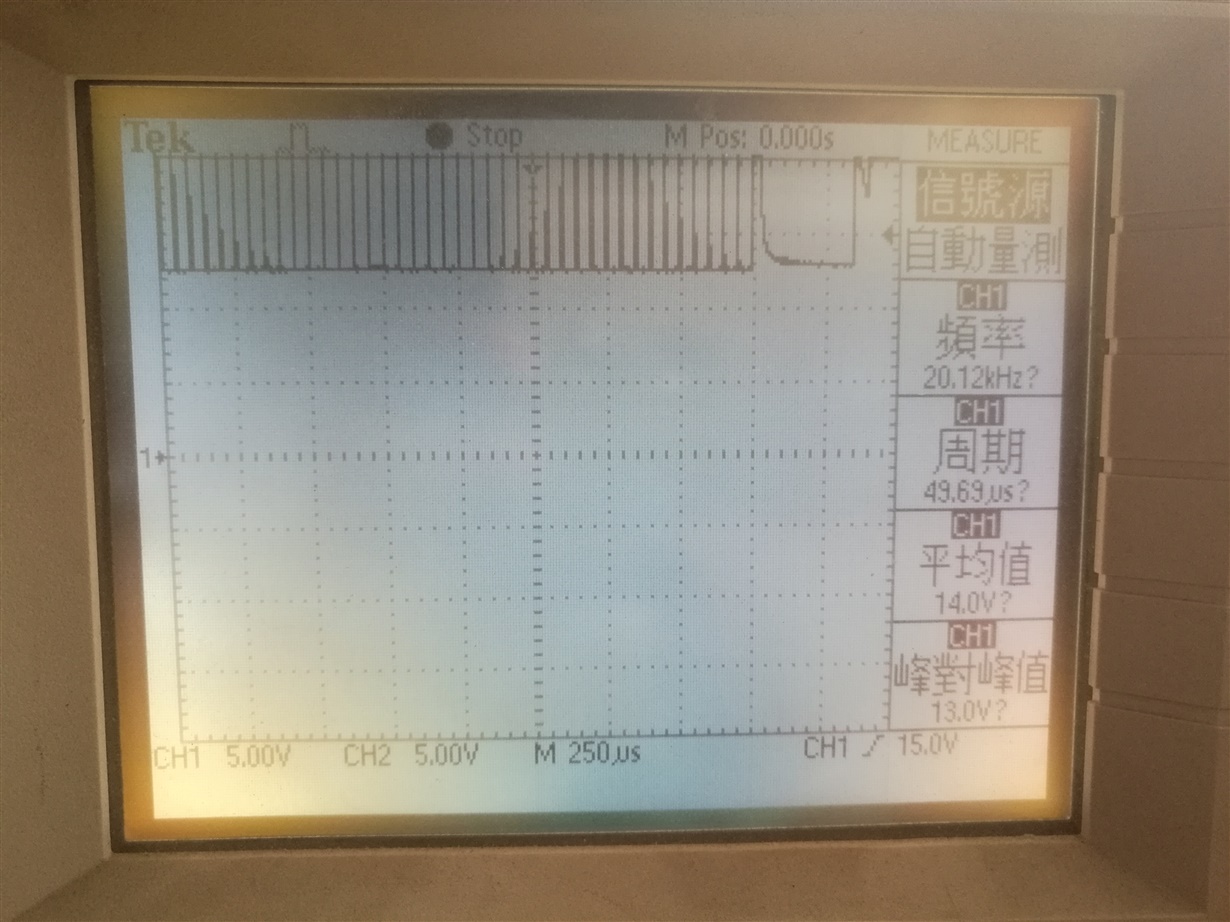
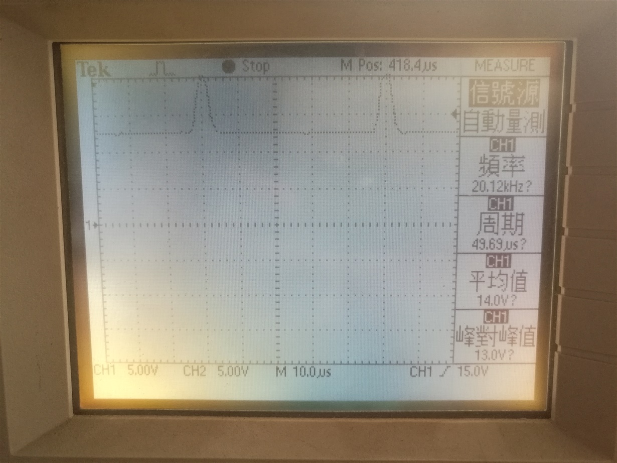
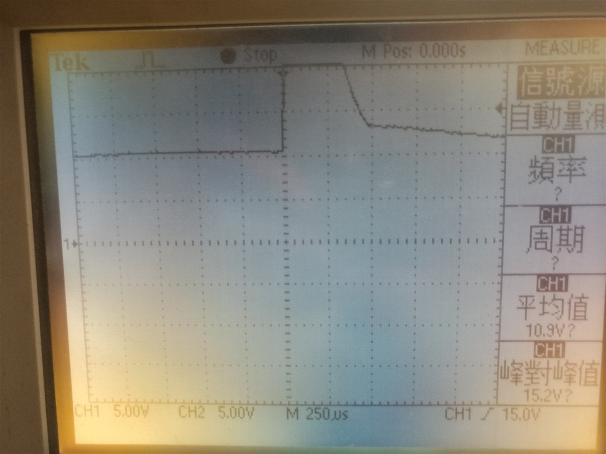
    My oscillator only has one channel can be used.  So the following is my description and pictures:

    The power voltage is 24V


                   EN_GATE=0      EN_GATE=1
    GVDD     0V                      11V
    BST_A    0V                      pwm-pulse, pulse-last, 10.6V
    BST_B    0V                      pwm-pulse, pulse-last, 10.6V
    BST_C    0V                      pwm-pulse, pulse-last, 10.6V

    picture:  pwm-pulse,  pwm-pulse amplify to 10us/div,  pulse-last

  • Hi user1416086,

    Which PWM mode are you using (6 or 3)?

    If 6 PWM mode, are you setting INL_x high/INH_x low to charge the bootstrap capacitor prior to setting INL_x low/INH_x high ?
  • Hi Rick,

    My PWM mode number is 6.

    My programmer is modified on the TI BLDC_SD project. The following is  some functions about BLDC PWM.

    ======================================================================

    f28035/dmclib/drvlib/f2803xbldcpwm.h

    ======================================================================

    #define BLDCPWM_MACRO(v) /* */\
    /* Convert "Period" (Q15) modulation function to Q0 */\
    Tmp = (int32)v.PeriodMax*(int32)v.MfuncPeriod; /* Q15 = Q0xQ15 */\
    Period = (int16)(Tmp>>15); /* Q15 -> Q0 (Period) */\
    /* */\
    /* Check PwmActive setting */\
    if (v.PwmActive==1) /* PWM active high */\
    GPR0_BLDC_PWM = 0x7FFF - v.DutyFunc; /* */\
    /* */\
    else if (v.PwmActive==0) /* PWM active low */\
    GPR0_BLDC_PWM = v.DutyFunc; /* */\
    /* */\
    /* Convert "DutyFunc" or "GPR0_BLDC_PWM" (Q15) duty modulation function to Q0 */\
    Tmp = (int32)Period*(int32)GPR0_BLDC_PWM; /* Q15 = Q0xQ15 */\
    /* */\
    /* State s1: current flows to motor windings from phase A->B, de-energized phase = C */\
    if (v.CmtnPointer==0) /* */\
    { /* */\
    EPwm1Regs.AQCSFRC.bit.CSFA = 0; /* Forcing disabledd on output A of EPWM1 */\
    EPwm1Regs.AQCTLA.bit.CAU = 2; /* Set high when CTR = CMPA on UP-count */\
    EPwm1Regs.AQCTLA.bit.ZRO = 1; /* Set low when CTR = Zero */\
    EPwm1Regs.CMPA.half.CMPA = (int16)(Tmp>>15); /* PWM signal on output A of EPWM1 (Q15 -> Q0) */\
    EPwm1Regs.AQCSFRC.bit.CSFB = 1; /* Forcing a continuous Low on output B of EPWM1 */\
    /* */\
    EPwm2Regs.AQCSFRC.bit.CSFA = 1; /* Forcing a continuous Low on output A of EPWM2 */\
    EPwm2Regs.AQCSFRC.bit.CSFB = 2; /* Forcing a continuous High on output B of EPWM2 */\
    /* */\
    EPwm3Regs.AQCSFRC.bit.CSFA = 1; /* Forcing a continuous Low on output A of EPWM3 */\
    EPwm3Regs.AQCSFRC.bit.CSFB = 1; /* Forcing a continuous Low on output B of EPWM3 */\
    } /* */\
    /* */\
    /* State s2: current flows to motor windings from phase A->C, de-energized phase = B */\
    else if (v.CmtnPointer==1) /* */\
    { /* */\
    EPwm1Regs.AQCSFRC.bit.CSFA = 0; /* Forcing disabledd on output A of EPWM1 */\
    EPwm1Regs.AQCTLA.bit.CAU = 2; /* Set high when CTR = CMPA on UP-count */\
    EPwm1Regs.AQCTLA.bit.ZRO = 1; /* Set low when CTR = Zero */\
    EPwm1Regs.CMPA.half.CMPA = (int16)(Tmp>>15); /* PWM signal on output A of EPWM1 (Q15 -> Q0) */\
    EPwm1Regs.AQCSFRC.bit.CSFB = 1; /* Forcing a continuous Low on output B of EPWM1 */\
    /* */\
    EPwm2Regs.AQCSFRC.bit.CSFA = 1; /* Forcing a continuous Low on output A of EPWM2 */\
    EPwm2Regs.AQCSFRC.bit.CSFB = 1; /* Forcing a continuous Low on output B of EPWM2 */\
    /* */\
    EPwm3Regs.AQCSFRC.bit.CSFA = 1; /* Forcing a continuous Low on output A of EPWM3 */\
    EPwm3Regs.AQCSFRC.bit.CSFB = 2; /* Forcing a continuous High on output B of EPWM3 */\
    } /* */\
    /* */\
    /* State s3: current flows to motor windings from phase B->C, de-energized phase = A */\
    else if (v.CmtnPointer==2) /* */\
    { /* */\
    EPwm1Regs.AQCSFRC.bit.CSFA = 1; /* Forcing a continuous Low on output A of EPWM1 */\
    EPwm1Regs.AQCSFRC.bit.CSFB = 1; /* Forcing a continuous Low on output B of EPWM1 */\
    /* */\
    EPwm2Regs.AQCSFRC.bit.CSFA = 0; /* Forcing disabled on output A of EPWM2 */\
    EPwm2Regs.AQCTLA.bit.CAU = 2; /* Set high when CTR = CMPA on UP-count */\
    EPwm2Regs.AQCTLA.bit.ZRO = 1; /* Set low when CTR = Zero */\
    EPwm2Regs.CMPA.half.CMPA = (int16)(Tmp>>15); /* PWM signal on output A of EPWM2 (Q15 -> Q0) */\
    EPwm2Regs.AQCSFRC.bit.CSFB = 1; /* Forcing a continuous Low on output B of EPWM2 */\
    /* */\
    EPwm3Regs.AQCSFRC.bit.CSFA = 1; /* Forcing a continuous Low on output A of EPWM3 */\
    EPwm3Regs.AQCSFRC.bit.CSFB = 2; /* Forcing a continuous High on output B of EPWM3 */\
    } /* */\
    /* */\
    /* State s4: current flows to motor windings from phase B->A, de-energized phase = C */\
    else if (v.CmtnPointer==3) /* */\
    { /* */\
    EPwm1Regs.AQCSFRC.bit.CSFA = 1; /* Forcing a continuous Low on output A of EPWM1 */\
    EPwm1Regs.AQCSFRC.bit.CSFB = 2; /* Forcing a continuous High on output B of EPWM1 */\
    /* */\
    EPwm2Regs.AQCSFRC.bit.CSFA = 0; /* Forcing disabled on output A of EPWM2 */\
    EPwm2Regs.AQCTLA.bit.CAU = 2; /* Set high when CTR = CMPA on UP-count */\
    EPwm2Regs.AQCTLA.bit.ZRO = 1; /* Set low when CTR = Zero */\
    EPwm2Regs.CMPA.half.CMPA = (int16)(Tmp>>15); /* PWM signal on output A of EPWM2 (Q15 -> Q0) */\
    EPwm2Regs.AQCSFRC.bit.CSFB = 1; /* Forcing a continuous Low on output B of EPWM2 */\
    /* */\
    EPwm3Regs.AQCSFRC.bit.CSFA = 1; /* Forcing a continuous Low on output A of EPWM3 */\
    EPwm3Regs.AQCSFRC.bit.CSFB = 1; /* Forcing a continuous Low on output B of EPWM3 */\
    } /* */\
    /* */\
    /* State s5: current flows to motor windings from phase C->A, de-energized phase = B */\
    else if (v.CmtnPointer==4) /* */\
    { /* */\
    EPwm1Regs.AQCSFRC.bit.CSFA = 1; /* Forcing a continuous Low on output A of EPWM1 */\
    EPwm1Regs.AQCSFRC.bit.CSFB = 2; /* Forcing a continuous High on output B of EPWM1 */\
    /* */\
    EPwm2Regs.AQCSFRC.bit.CSFA = 1; /* Forcing a continuous Low on output A of EPWM2 */\
    EPwm2Regs.AQCSFRC.bit.CSFB = 1; /* Forcing a continuous Low on output B of EPWM2 */\
    /* */\
    EPwm3Regs.AQCSFRC.bit.CSFA = 0; /* Forcing disabled on output A of EPWM3 */\
    EPwm3Regs.AQCTLA.bit.CAU = 2; /* Set high when CTR = CMPA on UP-count */\
    EPwm3Regs.AQCTLA.bit.ZRO = 1; /* Set low when CTR = Zero */\
    EPwm3Regs.CMPA.half.CMPA = (int16)(Tmp>>15); /* PWM signal on output A of EPWM3 (Q15 -> Q0) */\
    EPwm3Regs.AQCSFRC.bit.CSFB = 1; /* Forcing a continuous Low on output B of EPWM3 */\
    } /* */\
    /* */\
    /* State s6: current flows to motor windings from phase C->B, de-energized phase = A */\
    else if (v.CmtnPointer==5) /* */\
    { /* */\
    EPwm1Regs.AQCSFRC.bit.CSFA = 1; /* Forcing a continuous Low on output A of EPWM1 */\
    EPwm1Regs.AQCSFRC.bit.CSFB = 1; /* Forcing a continuous Low on output B of EPWM1 */\
    /* */\
    EPwm2Regs.AQCSFRC.bit.CSFA = 1; /* Forcing a continuous Low on output A of EPWM2 */\
    EPwm2Regs.AQCSFRC.bit.CSFB = 2; /* Forcing a continuous High on output B of EPWM2 */\
    /* */\
    EPwm3Regs.AQCSFRC.bit.CSFA = 0; /* Forcing disabled on output A of EPWM3 */\
    EPwm3Regs.AQCTLA.bit.CAU = 2; /* Set high when CTR = CMPA on UP-count */\
    EPwm3Regs.AQCTLA.bit.ZRO = 1; /* Set low when CTR = Zero */\
    EPwm3Regs.CMPA.half.CMPA = (int16)(Tmp>>15); /* PWM signal on output A of EPWM3 (Q15 -> Q0) */\
    EPwm3Regs.AQCSFRC.bit.CSFB = 1; /* Forcing a continuous Low on output B of EPWM3 */\
    }

    #endif // __F280X_BLDCPWM_H__

  • Hi,Rick

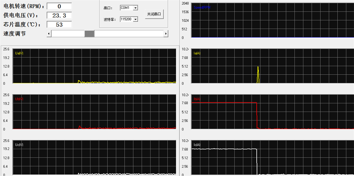
    The following  is the  wave  picture of motor booting  captured by the com  port of PC.

    The motor can only run one step, and then stop.

    Ib and Ic is used, Ia is not used.

  • Hi Rick,

    I have test my programme(open loop) on the BOOSTXL-DRV8301 board, it can drive the motor normally.

    It must be a hardware  problem.

    How can I test the chip of DRV8301? Maybe it has been damaged.

  • Hi user1416086,

    Sorry for the delay. I suggest you compare the signals of the BOOSTXL-DRV8301 with your board to determine why your board is acting incorrectly.