This thread has been locked.

If you have a related question, please click the "Ask a related question" button in the top right corner. The newly created question will be automatically linked to this question.

DRV8834 1/2 stepping or micro stepping issues

Other Parts Discussed in Thread: DRV8834

Hi Team,

The customer is using DRV8834 at full step mode and their motor will move 1mm per full step. This is working perfectly fine.

However,​they need to achieve 0.5mm motor movement per step. So they are trying to use half step mode, making M1 as 0 and M0 as 1. When they are

​testing this, for the first pulse motor is moving, and for the second pulse motor is not any movement. they found it is working alternatively for ​every ​pulse on half step mode.
​Also when they try 1/4 step mode, for the first pulse motor is moving ,and​ for ​the next 3 pulse motor is not any movement.
What is the reason? How to solve the issue?
Thanks,
Best Regards,
  • Hi Mickey,

    Can you provide a scope capture of the current when moving?
    What is the motor model and specifications?
    Is there a gearbox on the motor?
    What is VM, the decay mode setting, VREF, and the sense resistor value?
  • Hi Rick,

    Thanks for your reply.  Here are the customer's  reply.

    1.Can you provide a scope capture of the current when moving?

    Do you mean an oscilloscope capture of AOUT1 wrt to AOUT2, and similarly for BOUT. 

    Or is this current across sense resistor. Can you advise on this?

    2. What is the motor model and specifications?

    20DAM20D1B-K is our motor part number and is from portescap. I have attached specs of 20DAM motor below.

    3. Is there a gearbox on the motor?

    Yes,it is a stepper motor (15 ± 1 degree) based can stack linear actuator. This degree is converted to 0.05mm linear movement by gears internally by motor manufacturer. 

    4. What is VM, the decay mode setting, VREF, and the sense resistor value?

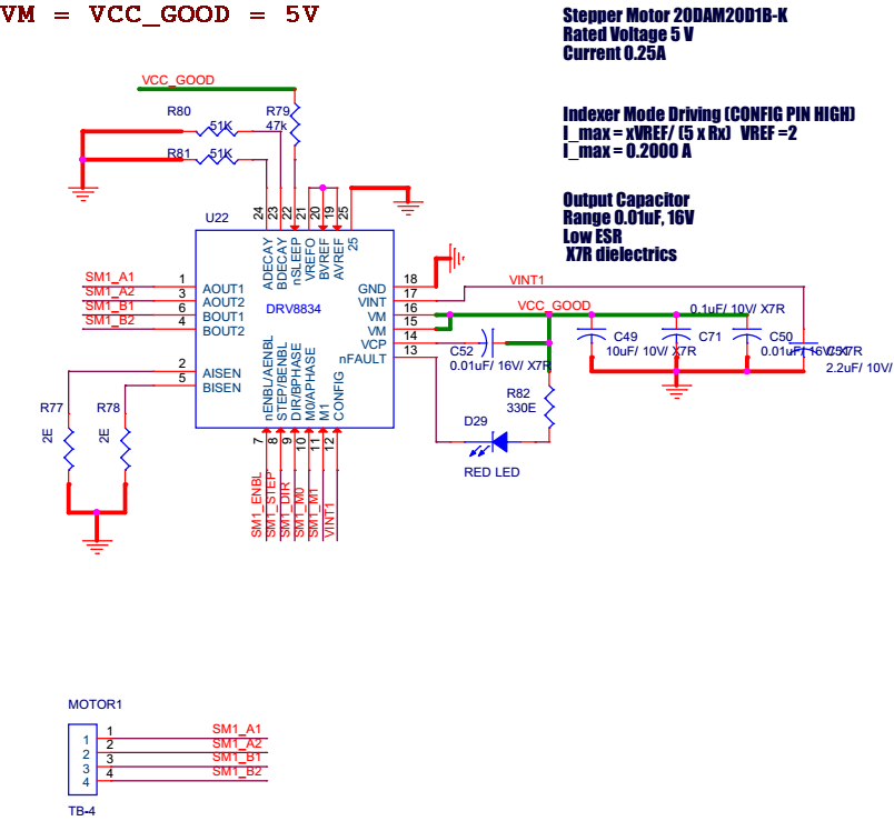
    ​ VM is connected to 5V, Resistance on both decay Pin are 51Kohm, VREF is 2V and is shorted with ​BVREF and AVREF. Sense resistor is 2Ohm to limit current to 0.2A (motor rated current is 0.25A).

    20DAM_K_specifications.pdf

  • Hi Rick,
    Can you see my answers? The customer is waiting for my reply.
  • Hi Mickey,

    Yes, I can see your answers.

    1.Can you provide a scope capture of the current when moving?

    Do you mean an oscilloscope capture of AOUT1 wrt to AOUT2, and similarly for BOUT.

    Or is this current across sense resistor. Can you advise on this?


    Ideally, use a current probe to measure the current. If this is not available, please capture the voltage across the sense resistor.

    You may find the average current is less than desired.

    Can you try changing the xDECAY resistors to 20K. This will increase the average current.

    It would also be good to check with the motor manufacturers to confirm the motor can achieve the desired movement. If it cannot, the DRV8834 cannot correct this.

  • Hi Rick,

    Here are the customer's reply.

    1.Ideally, use a current probe to measure the current. If this is not available, please capture the voltage across the sense resistor. You may find the average current is less than desired.

    We measured voltage across current sense resistor, Voltage is 280 mV, and sense resistor is 1.8 Ohm, hence current is 155 mA.

    2.Can you try changing the xDECAY resistors to 20K. This will increase the average current. It would also be good to check with the motor manufacturers to confirm the motor can achieve the desired movement. If it cannot, the DRV8834 cannot correct this.

    We changed it to 20 K, and me measured voltage across current sense resistor, it is as attached below
    Voltage is 288 mV, and sense resistor is 1.8 Ohm, hence current is 160 mA.
    I got confirmation from motor manufacturer that it will support micro stepping.

    3. Also one more thing we noted, once firmware is loaded to micro controller DRV8834 is active (we are making n_sleep high default) and hence we can hear a noise sound (very small) from motor, In half step operation for first step motor is moving and same noise is there from motor, on next step no movement and also the noise from motor stops. On next pulse motor moves and noise will be back and then vice versa.

  • Hi Mickey,

    Sorry, I was not clear about the voltage across the sense resistor. I would like to see a scope capture of the voltage across both sense resistors when the motor is moving. Please zoom in to show 8 steps in 1/2 step or 16 steps in 1/4 step mode.

    The noise in 1/2 step can be caused by interaction between the two coils in the motor. In one step, current is flowing through both coils. In the next step, current is flowing through one coil and the other coil has no current.
  • Hi Rick,
    The customer has replied me.

    Please find scope capture of 8 steps in 1/2 step which is working fine. Look the attachment.

    But issue is when 1 steps in 1/2 steps. Please find the scope capture of this


    This scope reading is not consistent at 1 steps in 1/2 step. Every alternate 1 step is working (but motor is moving same as full step) in 1/2 step as i mentioned earlier.

    The customer tried alternate motor from another manufacturer also, still same problem, motor manufacturer says it support all microstepping operations.

  • Hi Mickey,

    Can you confirm the first scope capture is 1/2 steps? It is expected to see voltage across the sense resistor 3 times as long as no voltage.

    Please ask the customer to provide the voltage of both sense resistors in the same scope capture. If possible, please include the step pin voltage.

    The scope captures provided do not include step information. This is needed to determine when the current should change.
  • Hi Rick,

    The customer has sent the   capture across both sense resistors in the same scope capture. Look the attachment.

    Motor_microstepping.docx

  • Hi Mickey,

    Thanks and sorry for the delay.

    Unfortunately, the first three scope captures are zoomed in too much. These scope captures show the PWM frequency of 42kHz, but it does not show the difference in current between the steps.

    The second three provides the desired information. The current below is a rough average based on the PWM frequency and the voltage on the sense resistor.
    First single half step shows 0% in the first coil and an average of 165mA in the second coil.
    Second single half step shows ~80mA average current in both coils.
    Third single half step shows an average of 165mA in the first coil and 0% in the second coil.

    Can you ask the customer to try using a 1kOhm resistor on the decay pins? This will provide more torque at each step.
  • Hi,
     
    As suggested we tested with 1kOhm resistor on the decay pins,  but result is same. I have attached scope capture of three 1/2 steps. 
    1. Motor is moving for first 1/2 step
    Inline image 1
    2. Motor is not moving for next 1/2 step
    Inline image 2
    3. Motor moves again
    Inline image 3
     
    Is there any other parameters that we can check out.
     
    Regards
    Justin
  • Hi Justin,

    The images did not appear. Can you resend them?
  • Yes, Please find the images again attached here in the same order 1) motor moving 2) no movement 3) movement observed 

  • Hi Justin,

    Sorry for the late reply.

    There are two items to point out:

    1) The current regulation appears to be lower than expected. The current chopping should be either at 400mV (200mA) or 280mV (140mA) for a 200mA current. The waveforms show current chopping at 280mV (140mA) and 200mV (100mA).

    2) Without a current probe, it is impossible to determine the average current at each step. This could be the reason for the missing steps.

    I contacted the motor manufacturer. They also believe the current is not being regulated properly.

    If the customer would like to try something, change the sense resistors to 1.1 Ohms. This set the full scale current at 260mA (RMS current per winding of 250mA. This may provide the necessary torque to move the motor properly.