This thread has been locked.

If you have a related question, please click the "Ask a related question" button in the top right corner. The newly created question will be automatically linked to this question.

DRV8711 - Stall Pin Strange Behavior

Other Parts Discussed in Thread: DRV8711

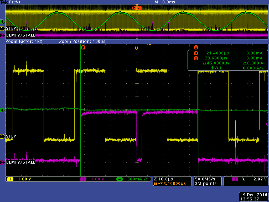
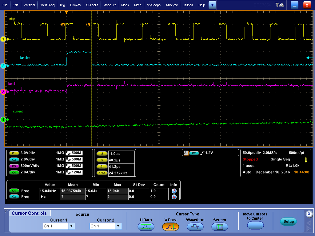
I'm seeing some strange behavior on STALLn / BEMFVn pin 19 with 256 microsteps.  In my scope screen shot, purple is the STALLn/BEMFVn pin.  You can see it transitions active low twice within 45us.  In this example I'm running at 50 RPM which, for my motor, is 42,666 pulses per sec or 23.4us per pulse.  That being said, it looks like the DRV8711 is rearming and signalling back-to-back BEMFVn measurements after the zero current step.  What would cause this?  Am I pushing up against the frequency limit of the DRV8711 by trying to run at 42.6kHz?  I don't think I'm even close to the frequency limit because the spin guide talks about running upwards of 400kHz.

If I double the speed so it is 100 RPM, the behavior doesn't change except the two active low transitions occur in half the time.  In my scope screen shot, the yellow signal is my SPI clock which is clearly staggered in-between each zero current step, so I'm convinced the double active low transition on the stall pin is not due to me reading/writing to the DRV8711 STATUS:SDTLAT bit to clear the SDT bit and STALLn / BEMFVn pin, in preparation for the next back EMF sample.

This double active low edge on the STALLn / BEMFVn pin is causing problems in my system because I'm running in external stall mode so my microcontroller is taking BEMF measurements every time it sees an active low transition.  I'm using the measurements to adjust torque, so having two adjustments in one step is not ideal for my application, especially since the measurements can not be accurate since one of the active low transitions spans outside of a zero current step.  If I change to 128 microsteps but keep the speed at 50RPM, I get a single active low transition at each zero current step like I would expect.  Below I have include a second screen shot which shows the STALLn pin (purple signal) in relation to the STEP input (yellow signal) at 256 microsteps 50RPM.

1.) First screen shot: YELLOW = SPI Clock from Microcontroller, PURPLE = DRV8711 STALLn / BEMFVn, GREEN = Current Probe on Motor Coil

2.) Second screen shot: YELLOW = STEP input to DRV8711, PURPLE = DRV8711 STALLn / BEMFVn, GREEN = Current Probe on Motor Coil

  • Hi Chris,

    We will investigate this. It may take a couple of days.

    Please note the BEMF measurement is dependent on the step input frequency, the microstep mode, the motor parameters, and system system voltage. If there is not enough time during for the current to decay to zero during the step, the sample may not be valid.
  • I've noticed particularly when I make sudden large increases in torque, with the DRV8711 in external stall mode, the STALLn / BEMFVn output pin used to signal when a valid back EMF measurement is ready remains low and stops responding.  If I then lower the torque, sometimes I can get it to start making active low transitions again.  I'm really curious for any ideas of what could prevent the STALLn / BEMFVn output pin in external stall mode from signalling a valid back EMF measurement is ready.  What actually drives STALLn / BEMFVn output pin active low?  Is it just a counter or is there additional logic that could be susceptible to electrical noise from current surges?  Could the counter get corrupted?  Or maybe is it possible the back EMF signal could somehow cause the STALLn / BEMFVn output pin to malfunction?

  • Hi Chris,

    This thread will be merged with your prior post. I hope you don't mind.

    We will discuss this with the design team and get back to you.
  • Hi Chris,

    Sorry for the delay. We are not sure of the reason for the double pulse, but there is a more fundamental problem. <-- edited to add the word not)

    At the current 42,666 pps,the results from the BEMF is not valid. If the step pulse is less than ~110 us (this may vary depending on the motor), the current is not sampled properly. You can see this in the following images.

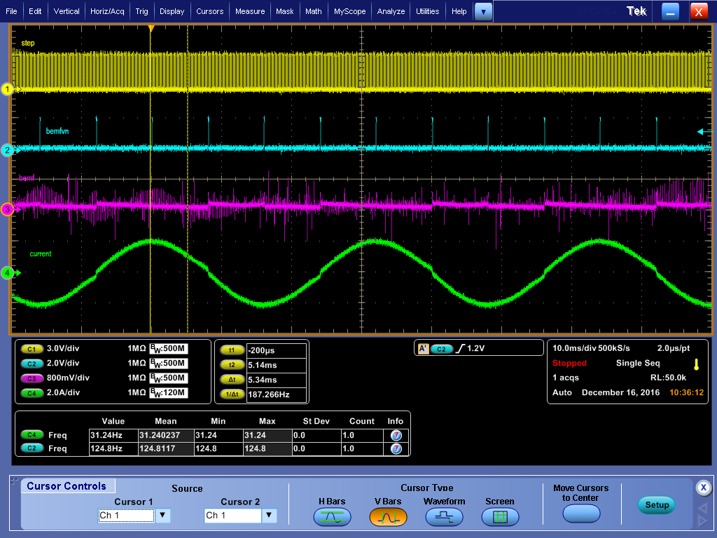
    At 8k pps, the BEMFVn signal drops before the next step pulse indicating the sample is valid. The first image is zoomed out to show that BEMFVn occurring at the zero and 100% current (zero current in the winding not shown).


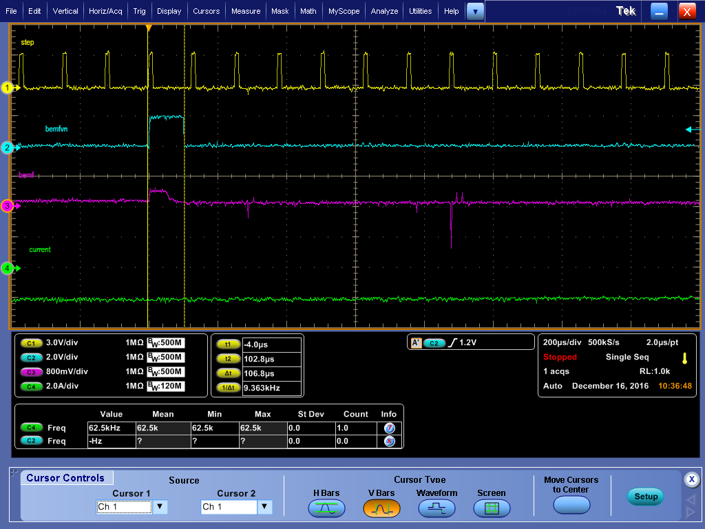
    This image is the zoomed in version of the one above (8k pps) to show that BEMFVn is asserted prior to the next step pulse.

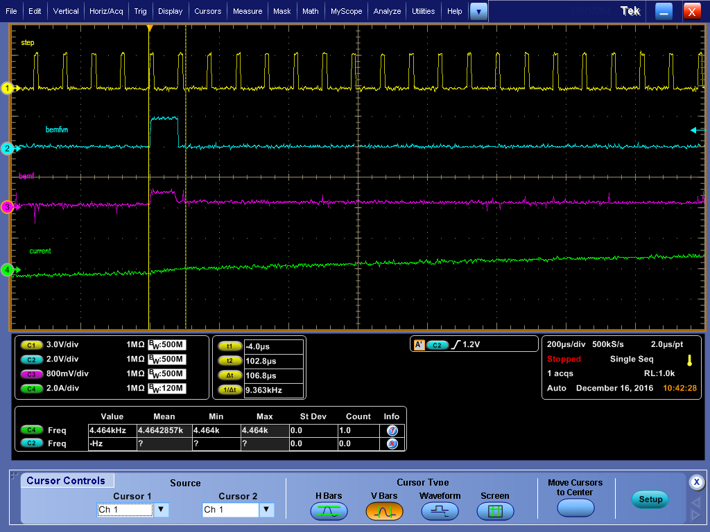
    The image below is the zoomed in version at 12k pps to show that the BEMFVn is terminated at the start of the next step pulse.

    The image below is the zoomed in version at 24k pps to show that the BEMFVn is terminated at the start of the next step pulse.

    To achieve valid back emf information, please try lowering the microstep rate such that the pps are approximately 8k or less.

  • I see what you mean.  From your scope captures, it looks like the DRV8711 must be given enough time to transition BEMFvn signal low again before the next step occurs, otherwise the measurement is invalidated.  8k is pretty slow though and in the audible range for human hearing.  The only way to achieve a pps lower than 8k for our motor running at 50RPM would be to reduce to 32 microsteps.  This will be much noisier.  We prefer to run 20kHz or higher to minimize audible noise and provide smoother operation.  In the DRV8711 datasheet it says the maximum step frequency is 250kHz.  I don't see mention of 8kHz limitation you speak of--why?

  • Hi Chris,

    I have edited my reply. It should have said "We are not sure of the reason for the double pulse"
  • Hi Chris,

    The output PWM frequency at 8k pps input is not 8kHz. Once the current reaches the required level, current regulation begins. This will PWM the output at a rate that is typically less than 1/(tblank + toff). The tblank and toff can be adjusted to increase or decrease the output PWM frequency.

    Please refer to sections 7.3.5 and 7.3.6 for more details.
  • Rick,

    I work with Chris.  (NOTE: The chip is setup in Indexer mode and External Stall Detect mode.)

    You said "The tblank and toff can be adjusted to increase or decrease the output PWM frequency."

    Now I see. Originally, we thought the PWM frequency (ƒPWM) was determined from the STEP input frequency (ƒstep = ƒPWM ).

    And, we have had very good success changing TOFF along as we change the motor speed (ƒstep ) to ensure that:

    TBLANK + TOFF + (2 × DTIME) <≈ 1/ƒstep (Hz)        ;  (instead of fpwm)

    Clarifying my understanding from the following:

    7.3.4  After the off time expires, the bridge is reenabled, starting another PWM cycle

    7.3.5 If the Itrip level changes during a PWM cycle (in response to a step command to the indexer), the current cycle is immediately terminated, and a new cycle is begun.

    Therefore:

    PWM cycle Starts: STEP to the indexer, or after tOFF expires.
    PWM cycle Stops: when tOFF expires, or immediately on STEP to indexer (to start a new cycle)

    I now see that we were basically ensuring that the minimum PWM frequency was less than that step frequency as we change speeds.
    Any guidance here?  How much can fPWM vary with the same TBLANK, TOFF and DTIME setting ?

    regards,

    Michael

  • Despite having a step frequency of ~3,413 pulses per second (~292 micro-sec pulse period), I am still having issues with the stall pin giving two pulses at every zero current step.  This is about 4 RPM with my 200 step/rev motor.  Your previous post said to keep the STEP pin period more than 110 micro-sec so because this example is much more than that, I should have an accurate BEMF measurement.  You said the 110 micro-sec limit can vary depending on the motor but, I see the same behavior without the motor connected.  

    I am not writing to any bits in the STATUS register so I'm expecting the STALL pin to assert and clear itself.  According to the data sheet, the STALL pin is active-low, so I'm expecting to see a voltage equal to VCC when the BEMF measurement is ready and GND otherwise.  

    Interestingly, I only see the double pulse when CTRL[MODE] is set to 256 micro-steps.  If everything else stays constant and I just change CTRL[MODE] from 256 to 128 micro-steps, the STALL pin works as expected -- only one pulse every zero current step.

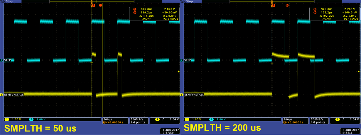
    Although it might be unrelated, I want to point out that the only register write that seems to effect the timing of the double pulse is TORQUE[SMPLTH].  This screen capture shows the STEP pin input in blue and the BEMFV/STALL pin output in yellow.  The image on the left is when TORQUE[SMPLTH] = 50 micro-sec (the minimum) and the image on the right is when TORQUE[SMPLTH] = 200 micro-sec.  It seems that the width of the pulse changes according to how TORQUE[SMPLTH] is set which is what I would expect.  I don't think this has anything to do with the problem but all other register writes (besides CTRL[MODE]) do not have any effect on the double pulse.  That being said, this is starting to appear to me like a quirk with the DRV8711.  Any thoughts?