This thread has been locked.

If you have a related question, please click the "Ask a related question" button in the top right corner. The newly created question will be automatically linked to this question.

DRV8432: Vreg=0.48v

Part Number: DRV8432

I am using DRV8432 first time for a motor control application.

Gvdd=vdd=12v,Pvdd=12v.

I am working in 1PFB mode.M0=0,M1=Vreg,M3=0.RESET_CD=0v.Reset_AB=NC.PWM_B and PWM_B=0.

After power is switched on voltage on I get Fault pin=0, OTW=1.65V, Vreg =0.48 .

Connecting RESET_AB to 0v. doesn't make any difference.

Unable to get device working.

Unable to locate the fault.

Please help.

  • Hi Mak,

    With the inputs configured as stated, the outputs should be disabled. Have you measured resistances between PVDD, GVDD, VDD, VREG, BST_x and GND? Is it possible to slowly raise the voltage on GVDD, VDD, PVDD and determine the current?

    Do you have a load connected after the power is switched on? If the load is connected, please disconnect the load and try enabling the outputs. Do you get the same results?


    It is recommended to turn the low side FET on for at least 50ns during each PWM cycle to avoid BST_UVP.


    Once you move pass the existing issue, please note section 7.4 of the datasheet. In PFB mode setting RESET_AB/ or RESET_CD/ to low resets all four outputs.
  • The resistances are as follows:-

    • PVDD-GND=Goes on increasing capacitor charging behavior
    • GVDD-GND=6.7K
    • VREG=GND=5.39K
    • BST_A=BST_B=BST_C=BST_D=Goes on increasing capacitor charging behavior

    Load is not connected.

    Replaced the device.


    But still same voltage coming on vreg pin.

  • Hi Mak,

    Were you able to slowly power up GVDD, VDD, and PVDD while measuring the current? This

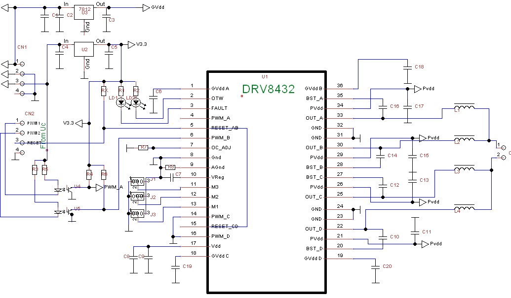
    Can you provide a schematic of the connections around the DRV8432?
  • Hi Mak,

    Thank you for the schematic.

    The output of the regulator does not appear to be connected to VDD (pin 17) and the GVDDx. Please confirm that it is connected properly.


    Please note figure 8 of the datasheet.
  • Though not shown in schematic. it is connected on the PCB

  • Figure 8 shows Full Bridge Mode Operation. I need to work it in Parallel Full Bridge Mode Operation.

    Unable to find the fault.

    Getting frustrated.

    Please help.

  • Hi Mak,

    Did you create your own schematic symbol and layout footprint?

    If you did, would you please go to www.ti.com/.../quality and create the CAD/CAE symbols using the .bxl file. Once created, please compare these with the ones you created?

    If the schematic and layout of the DRV8432 match, would you please provide your layout and an updated schematic?
  • Thanks Rick.It was my  mistake, as you pointed out. footprint was wrong.

    I updated the schematic with new footprint.

    Now voltages are proper.

    My objective is speed control o f 12v 120w dc motor. I am using dspic30f4011 controller.

    To test the circuit I connected small DC motor.

    I tried to drive it at various duty cycles. fault led blinks at lower duty cycles (at lower speed) but the motor rotates .Device gets warm after  a minute or two.

    But  when I connect the actual motor. only Fault Led blinks.motor never rotate.

    What is going wrong?

    Voltage at OC_ADJ=1.18v