Hi,
We have a product that uses the stall detect to find the end-stops for a stepper motor upon power up. The system was working for the first prototypes but the first sample production run had a 4 out of 10 that do not correctly detect the stall.
Our motor has a relatively high inductance (68mH/22Ohm) and the maximum SMPLTH value of 1ms is just barely long enough even at half stepping but it looks like it should be functioning but it isn't. We would like to set the SDCNT to 4 steps but have it set to 1 for troubleshooting.
Step rate is approx 1.2ms
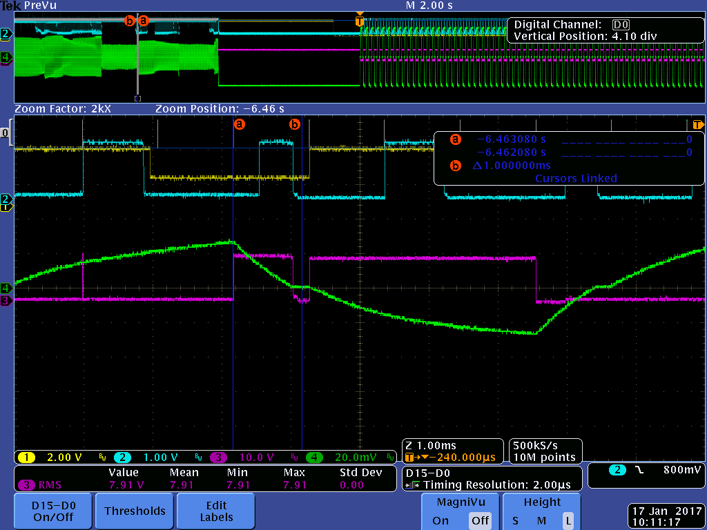
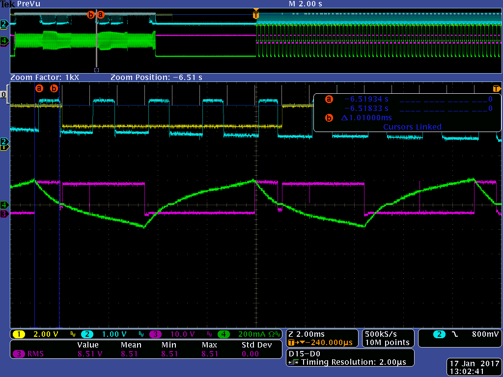
I have included a scope trace showing the problem.
Ch0 - Step input pulse
Ch1-Yellow, nStall
Ch2, Blue, BEMF
Ch3, Pink, Motor phase voltage - zero current step
Ch4, Green, Motor phase current - zero current step.
Blue cursors - showing 1mS window after zero current step pulse
The sample threshold is set about 1/4 full scale.
What appears to be the problem is that the BEMF sample occurs at the wrong time. In the example below cursor a is at the step input. 370uS later the BEMF goes high (this time does not seem to be associated with anything. 1ms from the step when the BEMF should be sampled the BEMF pin goes low again. It appears that when the BEMF goes high the next step the nStall pin goes high. If SDCNT is set above 0(1 step) the stall pin never goes active.
On a working board the nStall pin stays low for the entire stall event.
We have tried changing step rates, lowering the current so the PWM actively limits the current (not desirable because we want max torque) Trying other microstepping levels, changing the voltage threshold, changing the decay rates. Nothing seems to help.
We have considered keeping the SDCNT at 1 step and implementing our own stall counting algorithm but since the problem isn't' fully understood it is not sure if that will be a robust solution.


