This thread has been locked.

If you have a related question, please click the "Ask a related question" button in the top right corner. The newly created question will be automatically linked to this question.

DRV88xx - Current sense input: absolute maximum rating and protecting the SENSE input?

Other Parts Discussed in Thread: DRV8816, DRV8870, DRV8880

Team,

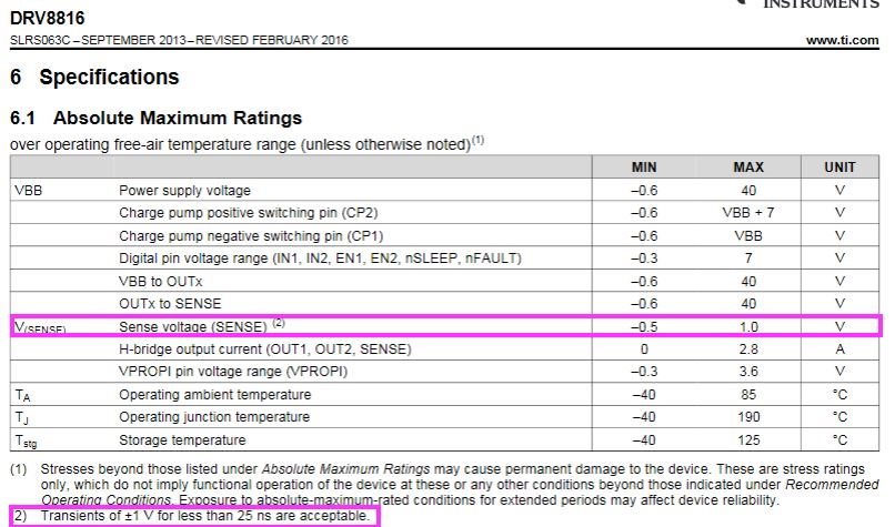
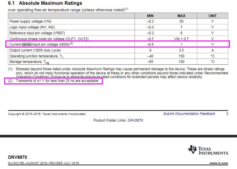
In most of the DRV88xx devices the current sense input voltage (SENSE on DRV8816, ISEN on DRV8870, AISEN on DRV8880) seems to be have a transient requirements (see below pictures from datasheet):
-voltage should not exceed 1V
-transient should not exceed +/- 1V/25ns
It seems that often in the real world some spikes could occur and the voltage on the sense input could exceed the the absolute maximum rating we specify.

Q: What do we advise to ensure that rating is not exceeded? Do we have some specific guidelines for filtering (like dimentioning a capacitor to filter the spike)?
Q: Could we highlight this requirement a bit more so that it is not overlooked?

Thanks in advance!

Anthony

-----------------------------------------------------------------------------------------------------------------------------------------
  • Hi Anthony,

    Thank you for your feedback.    

    This spec is intended as a DC specification, meaning sustained voltages of greater than 1 V on the SENSE pins will damage the device.  The footnote is to specify for transients.  These devices will not have an issue with spikes often observed in normal motor control applications where the abs max current spec is not being exceeded. 

    We don't specify any type of filtering / TVS clamp circuits on these pins because for most applications this would be unneeded and cause unwanted delay in the OCP / current chopping circuits inside of our device, meaning we would not accurately regulate current.  

  • Hi Phil,

    Thanks for the feedback. From your answer I understand that we do not recommend filtering/clamping on the SENSE pin.

    Here is the customer configuration below. Since the SENSE pin driver got damage over time a workaround was needed.

    -Our motor have a small snubber on the brushes, and we use to place a small LC filter on the output of the drive, causing perhaps a spike on the sensing resistor, despite the blanking time of some uS, causing early swith-off.
    -In our application the current limit is quite low : 0.4A resulting in ‘a sensitive’ feedback.
    -At this moment a 1uF over 0.75 Ohm sensing resistor solves 95% of the problems, I decided to place a 2.2uF (time delay of about 1.6uS).

    Any comments or concerns/risks about the above config?
    Thanks in advance!

    A.