This thread has been locked.

If you have a related question, please click the "Ask a related question" button in the top right corner. The newly created question will be automatically linked to this question.

DRV8432: Using as a PWM Controlled Rectifier

Part Number: DRV8432

Hi,

I am using a DRV8432DKD in 4 H-Bridge configuration to rectify 13 VAC to 35 VDC with a 100 ohm Load in a TI Dual motor control + PFC Board. I am only using the DSP and the motor driver (not the PFC part). However when I am connecting the external 12 VDC Power supply for the DSP and the driver, the reset pin automatically gets a bias of about 1.5 V. Also, when I am connecting the AC supply, instead of seeing a rectified DC voltage of about 17 V I am seeing very small voltage. When I remove the DSP card, the reset pin gets to low and the Voltage in the DC bus becomes as expected. I have tried to calculate the DSP current draw in the reset pin and also tried to change the pull down resister but it did not work. Any suggestion or information regarding this would be very helpful.

Thanks,

  • Hi Somsubhra,

    Can you provide some additional information? Are you using your design or a TI EVM? If a TI EVM, which one?

    Assuming it is your design:
    Have you double checked your schematic and layout?
    Do you have multiple boards to try?
  • Hi Rick,

    Thanks a lot for your quick reply. I am using the TI Dual motor control + PFC Board (www.ebay.com/.../161955447065 (Sorry the Ti Link was broken) Now I am trying to do a simple verification test before I use my other custom made board so right now its just the EVM. I guess the primary concern I have is whether it is possible to use the DRV8432 to drive as a rectifier. Since Ti made it to provide power from the DC to drive motor in the AC side and I am using AC input to create a stable DC output.

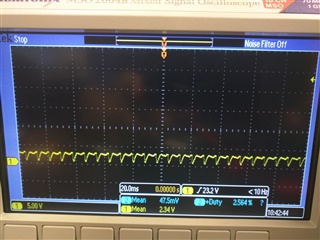
    This is the DC bus Voltage when the controller is not powered on.

    and this is the same voltage when the controller is powered on but not programmed. I guess this could happen with garbage values in the GPIO. But even after I program it to pull the Reset pin to low it still behaves in the same way. However when I try to use it as a simple inverter by providing DC input at the DC bus, it works just fine. So, my question is that is it even possible to use DRV8432 as rectifier?

  • A little bit more details to add. After further testing, it seems that when the chip is not supplied with the 12 V at GVDD_X pins, the IGBTs operate just fine, I mean they behave as a diode bridge. However, when ever the 12 V is turned on, the RESET_XX pin automatically gets a bias. So to further refine the question, is the Protection and I/O Logic part of the chip susceptible in any way to the an input AC? Since I have already tested the chip in inverter mode I am certain that it's operational.
  • Hi Somsubhra,

    Sorry for the delay. Where is the AC signal connected to the board? What AC voltage are you using?

    For reference, the link to the folder containing the schematic is C:\ti\controlSUITE\development_kits\LVMultiAxis+PfcKit_v1.4\~LVMultiAxis+PfcKit-HWdevPkg\LVMultiAxis+PfcKit-HWdevPkg[R3]

    assuming controlSUITE is installed in the default location. If installed elsewhere, the C:\ti\ will change.