This thread has been locked.

If you have a related question, please click the "Ask a related question" button in the top right corner. The newly created question will be automatically linked to this question.

DRV8701: About the fire of DRV8701.

Part Number: DRV8701
Other Parts Discussed in Thread: DRV8871

Thank you for your response.
I developed a motor drive using the drv8701p.
It is used in electric cars for children.

Sometimes, however, the drv8701p chip fires.
Where it occurs is concentrated in the VM portion of the drv8701p.

I need your help.

POWERPACK_EVL-1-4.pdf

  • I am using the DRV8701.
    Please tell me the solution to the lack of bulk capacitance of the VM supply.

    I sometimes have a fire.
    Applied products are children's electric cars.

  • Hi user4705198,

    Thank you for providing the schematic.

    Can you provide a few more details?
    What is the VM voltage?
    What decay mode do you use?
    Does the event occur in a specific use case?
    The schematic appears to be good. Can you provide a layout?
  • Hi Rick Duncan

    1. The VM voltage is 24V.
    2. Use the low-side slow decay mode of the DRV8701P (PWM) control.
         You may not understand the question. Is there another mode in the DRV8701P (PWM) Control?
    3. It does not occur during a specific use but occurs randomly.
    4. Attach the layout.

    Although not shown in the schematic, drv8871 is also on the bottom of the pcb (IC2)POWERPACK_EVL-1-4-top.pdfPOWERPACK_EVL-1-4-bot.pdfPOWERPACK_EVL-1-4-topsilk.pdfPOWERPACK_EVL-1-4-botsilk.pdf

  • Hi user4705198,

    A few more questions:
    Have any component values been changed from the schematic?
    Are you monitoring the nFAULT pin?
    Can you monitor the current when the event occurs?
  • HI. Rick Duncan

    The component values have not changed.
    The drv8871 used for steering is added to the same board.
    The nFAULT pin is not in use.
    The current at the event is unknown.
    We check the current through the SO pin through the process.
    (18Amp or more, shut off the power supply for more than 10 seconds).
    The process also reads the surface temperature of the MOSFET into the temperature sensor.
    (Pwm drive stops when it is 85 degrees or more).
    Events do not appear in Korea.
      It appears in exporting countries (USA, Mexico, etc.).

  • Hi user4705198,

    What is different about the countries? Do you have any idea why exporting countries would experience the event?
  • Hi Rick Duncan

    We do not know that there are other events with exporting countries.

    There is no difference in products.
    I think there is a difference in use environment only.

    Please advise us about the possibility that our circuit will have some problems in operation.
    I would also like to advise you on how to solve the problem.

    Thank you.

  • Hi user4705198,

    Sorry for the delay. This will be difficult to determine without understanding what if different.

    Can you monitor the VM voltage and determine if the voltage approaches the absolute maximum? Also please look at the SHx pins for positive and negative spikes.

    We have seen that adding lnon-zero series resistance in the GH and GL path can cause problems.
  • Hi Rick Duncan

    Thank you for your advice.

    Is monitoring the mv voltage the chip's vm pin?
    If so, can I configure a simple constant voltage (about 30V) circuit on the VM pin to avoid high voltage on the VM pin?
    I understand that this is not related to the difference in MOSFET supply voltage.
    We are working to reduce spikes on the motor side for the anode spikes on the SHx pin.
    Our circuit is GH, the resistance to GL path is 0 ohm.
    However, a small overshoot occurs when the MOSFET is turned on and off.
    This appears as noise on the supply power of the entire circuit.

    You may be busy, but I would like some advice.

  • Hi user4705198,

    Is monitoring the mv voltage the chip's vm pin?

    >> Please monitor the VM pin at the DRV8701 with respect to the GND pin at the DRV8701. Another area to monitor is the SHx pin with respect to the GND pin of the device.

    If so, can I configure a simple constant voltage (about 30V) circuit on the VM pin to avoid high voltage on the VM pin?

    >> Possibly, it depends on how you create the circuit.

    I understand that this is not related to the difference in MOSFET supply voltage.
    We are working to reduce spikes on the motor side for the anode spikes on the SHx pin.
    Our circuit is GH, the resistance to GL path is 0 ohm.
    However, a small overshoot occurs when the MOSFET is turned on and off.
    This appears as noise on the supply power of the entire circuit.
  • Hi!  Rick Duncan 


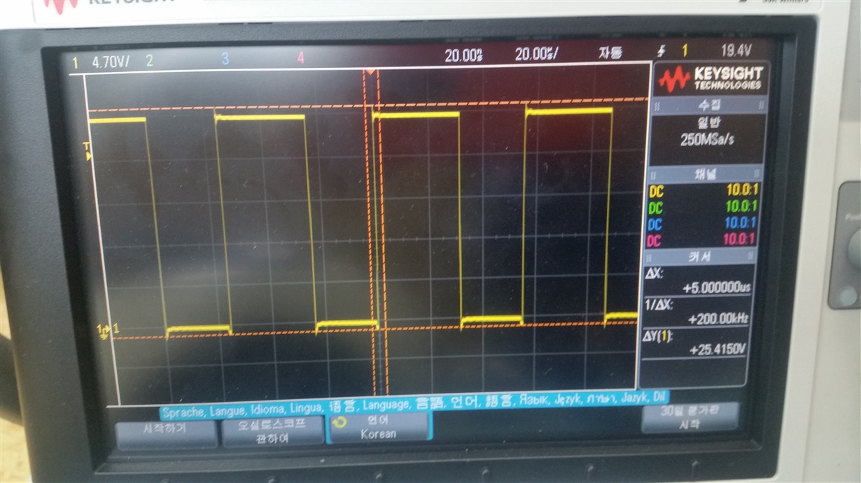
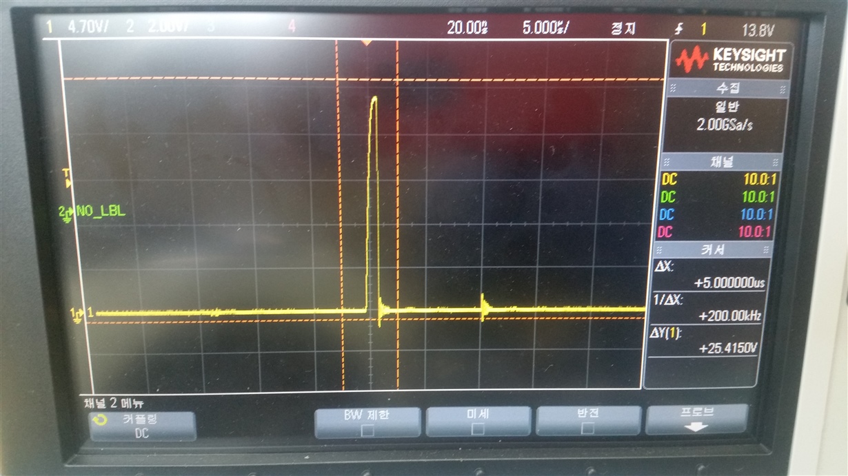
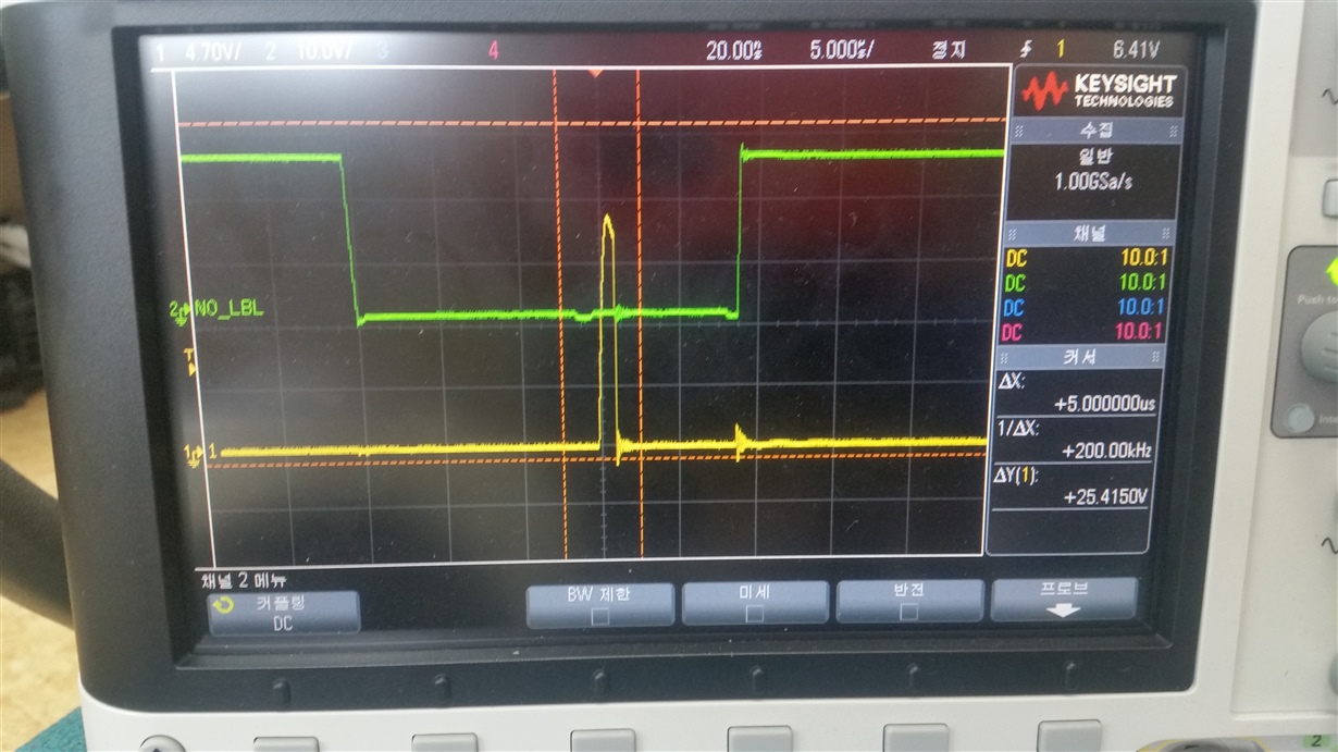
    The MV voltage is 25V at the input power of 25V.
    The pins of SHx are opposite in forward operation and reverse operation but do not exceed 25V maximum.
    This is the result of an oscilloscope.
    In addition, the waveform of the SHx pin of the PCB is attached.
    The third picture is a photograph of the SHx pin.
    The two photographs are SH1 and SH2 waveforms.
    Is the low pulse a brake / slow decay?