This thread has been locked.

If you have a related question, please click the "Ask a related question" button in the top right corner. The newly created question will be automatically linked to this question.

DRV595: Startup voltage issue

Part Number: DRV595

I have the circuit designed using DRV595. This circuit works fine under 13V input voltage. However, when the input DC voltage is above 13V, it cannot startup. I can start at 12V and then roll the voltage up to even 16V without problem. However, I do not know why I cannot directly start up at this voltage. The power supply I was using has been checked and it does not have any issue like overshoot. In addition, I do not have heavy load, since I was even trying to start up with no load but the issue still shows. Please suggest if possible. I have attached my schematic. Thanks!

  • Hi Lixing,

    Are you following the start-up sequencing from the datasheet?

    "To ensure proper operation on power up, wait 10ms after PVCC and AVCC are stable before using the analog inputs, IN– and IN+. Figure 14 illustrates this sequence."

    If you are, here are some things to check:

    When the device fails to turn on what is the voltage on the fault pin?
    How are you generating the 3V applied to IN-?
    Have you tried this on the EVM? Do you see the same problem?

    Regards,

    Alex
  • Hi Alex,

    Thanks a lot for your reply. Now I have removed the 3V at input and use a differential input. I have added some strong RC delay on the input so now the start up issue is solved. 

    But there are some more questions regarding the part:

    1. Will the driver limit duty cycle by itself? For example, when the voltage between IN+ and IN- is too large, will the output shut down or clamp at certain duty cycle? We have observed that when the input is too high, it can lead to fault.

    2. After the inductor output, what is the reason to have two common mode chokes? (The two caps from the two sides of load to ground) Do we have to have them in the design? What is the selection criteria?

    3. I am now using 1SPW mode, which means one half bridge is not switching. Do I still need the inductor connecting to it? Basically I am using the driver as a buck converter to generate DC output voltage (uni-direction)

    4. I will have about 2A of peak load current at 12V. Usually for this kind load, do you have an suggested PVCC decoupling capacitance?

    Thanks a lot!

    Lixing

    Alex Bhandari-Young said:
    Hi Lixing,

    Are you following the start-up sequencing from the datasheet?

    "To ensure proper operation on power up, wait 10ms after PVCC and AVCC are stable before using the analog inputs, IN– and IN+. Figure 14 illustrates this sequence."

    If you are, here are some things to check:

    When the device fails to turn on what is the voltage on the fault pin?
    How are you generating the 3V applied to IN-?
    Have you tried this on the EVM? Do you see the same problem?

    Regards,

    Alex

  • Can someone help answer my followup question? Thanks!
  • Hi Lixing,

    Sorry for the delay and thanks for following up. I had missed your previous post. I am looking into this now and will be posting shortly.

    Best,

    Alex
  • Hi Lixing,

    1) The device has over current protection which trips at 7.5A. It will shut down (output goes to high Z) if the output current exceeds this current limit, but this is determined by the output current and not directly by the input voltage level. The device has protection circuitry outlined on page 14 of the datasheet.

    2) I do not see a common mode choke at the output. However, the two caps from the two sides of load to ground you referred to are part of the output filter along with the inductor. The "OUTPUT FILTER CONSIDERATIONS" section of the datasheet provides some info for how the choice of cap value affects the filter. This app note is from our audio team, but provides some more detail on this type of filter www.ti.com/.../sloa119b.pdf
    What is your application for this part? This will have an effect on filter choice.

    3) The need for filters will depend on the application and how you are wiring the output. Would you be able to provide some more details? It is worth noting that in 1spw the bottom half bridge is switching when there is no output and is usually not switching when there is output. In normal applications like a TEC driver I believe you need both inductors.

    4) I wanted to clarify the questions from my previous post before commenting on what is causing the problem as I wasn't sure about your answers to them.

    Are you following the start-up sequencing from the datasheet? - It sounds like you changed the setup to meet the spec but still have the issue. Is this correct?
    How are you generating the 3V applied to IN-? - It sounds like you changed to a differential input and removed the 3V, but still see the issue. Is this correct?

    When the device fails to turn on what is the voltage on the fault pin? - I didn't see an answer to this in your last post. If I missed it could you please let me know.
    Have you tried this on the EVM? Do you see the same problem?

    Regards,

    Alex
  • Hi Alex,

    Thank you so much for your very detailed answer. I really appreciate it. You have answered most of my questions. Also by using super large RC delay to generate >10ms time, we are able to start up the driver without issue.

    For more details, my application is just a DC fan drive. I wanted to use DRV595 as a buck converter to generate a DC output voltage. The output voltage can be controlled linearly with the change of input reference voltage. The input is differential input with no ground shared with the DRV595. Now we still have two questions to ask:

    1. Since we are looking for a DC output to drive a DC fan, I would prefer to use 1SPW mode, which means I would only need one half bridge switching. Also, we are only having positive output. This means the driver can pretty much work like a buck converter. In this case, for the OUTN half-bridge, can I remove the inductor associated with it? This way would make it more like a buck converter.

    2. This question follows the last question: If we are using it as a buck converter, can I remove the two common mode caps after the output filter inductors?


    3. Our max load is about 2A, 12VDC. the current can have some 5-10kHz ripple with 0.5A amplitude. In this case, I am wondering what kind of input decoupling cap we will need.

    Thanks a lot!
    Lixing

  • Hi Lixing,

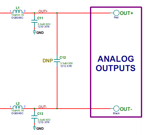
    About your question about the output filter, as Alex explained above, you have to reserve two inductor+capacitor filters for the OUT+ and OUT-. OUT- ouptut is still switching in 1spw mode for small input/output signal. But the common capacitor can't be remove. As the following picture showing, L1, L2, C11 and C13 can NOT be removed. But C12 can be removed. 

    For the power supply decoupling capacitor, you can use 220uF+0.1uF+1nF paralleled for PVCC. It works well on our EVM. For the hardware SCH&PCB design, please refer to our DRV595 EVM design http://www.ti.com/lit/ug/slau479/slau479.pdf It's a pretty good example.

    Best regards,

    Shawn Zheng

  • Hi Shawn and Alex. Thanks a lot and now it is much more clear for me now. I have no further questions. Thank you so much.