This thread has been locked.

If you have a related question, please click the "Ask a related question" button in the top right corner. The newly created question will be automatically linked to this question.

DRV8821: Mystery Overcurrent Tripping

Part Number: DRV8821

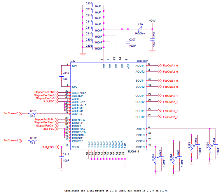
We use multiple DRV8821 components in one of our systems and we are evaluating a new motor for use on one of the circuits.  The circuit is configured for a maximum of 0.27A by using a 3Ohm resistor (with 100nF cap across it) on the sense pin.  Our original motor worked generally fine and has had very few issues with false tripping of the over current circuit.  However, in testing of the new motor we get over current tripping within 5 to 10 seconds of operation.  I feel confident it is over current tripping because the power must be cycled to return it to operation, and the chip itself does not feel warm or measure warm with an IR thermometer.

The original motor had 7.2mH of inductance and the new motor has 11mH.  VREF input has been tested at 3.5V and 4.0V.  At 3.5V it may be lasting slightly longer before it trips.  Current probing doesn't show anything of interest, the motor traces look like I would expect and I can see no difference between them.  With the original motor we have had a couple of boards where running the motors continuously for days would cause the over current to trip, but those have been quite minor.  Having them never trip would be better, but it was at a level that could be lived-with.  However, tripping within 5-10 seconds now has me hunting for a solution.

Relevant schematic portion is below.

Are there any other things that could be tripping this?  Since it is configured for a maximum of 0.27A, which I have confirmed by scope with a current probe, I am a bit stumped as to why it would be tripping.

Thanks for your help!

Dan

  • Hi Dan,

    The schematic appears to be OK. Based on your description, OCP is the most likely event. We will investigate and reply soon.

    While waiting, can you:

    capture the sense voltages 10us before the event occurs? The scope captures should be zoomed in to 2us/div if possible.

    lower VREF to 3.3V -- 0.22A?

    try reducing the 3 Ohm sense resistors to 1 Ohm and adjust VREF?

    Thank you.

  • Hi Rick,

    Thank you for the suggestions, I had been meaning to get probes on the Sense resistors and this gave me a good reason to.  I haven't caught any smoking gun traces yet, but I can see a bit of a spike when we enter a phase that decelerates one of the motors.  The newer motor also has larger mass so the back EMF in stopping will be larger.  I'm going to play with the deceleration speed and examine the impact on the traces.  I'll try a few more times to see if I can catch anything that should trip the 1.5A limit.

    Thanks!
    Dan

  • After lots of testing I was never able to catch a voltage that should have tripped it (1.5A into 3 ohms should be a 4.5V trip threshold) even with a 2us/division time scale (or longer or shorter), but I did manage to capture pulses up to a little over 2V which is much higher than the drive current (0.25A into 3ohms is 0.75A).  This corresponded directly to the back EMF I was investigating and I was able to capture a couple of times where it actually disabled the chip with a signal of 2 to 2.25V.  There is a possibility my wires or scope are somehow low passing what I'm measuring, but it is a 200MHz scope.

    Anyway, increasing the deceleration at the point of rapid speed changes made it easy for me to observe changes in the back EMF spike and get it spread out over enough time as the disappear into the normal motor current range of 0.25A.  Since I enacted the change I have not been able to get the chip to disable so I believe I have a working solution.

    To add some feedback on the chip it would be wonderful for the reset bit to be able to clear an over-current condition, a fault output would be extremely helpful to know the chip has disabled, and increasing the over-current value to at least 2.0A and decreasing the pulse sensitivity would be extremely helpful.  I do see many of these features in different motor control chips from TI so I will investigate those for future designs.

    Thank you very much for the help!

    Regards,
    Dan

  • Hi Dan,

    Thank you for your suggestions. We will added them to the list of improvements in future devices. The newer devices do have these abilities, but do not have the ability to control two steppers.

    There is a method that could be used to create a pseudo fault indicator for these events. By adding two high impedance resistors across the outputs to create 1/2VM, and a second resistor divider from 1/2VM to lower the voltage further to mcu input levels the outputs can be monitored to determine if they are still active. A protection circuit to limit the voltage in the case of one resistor opening should be considered. One circuit per motor would be needed.

    Example: Place two 100k resistors in series across the winding of one motor. Place a second divider of 12k from the middle of the two 1M resistors and 4k to GND. The center of this second divider should provide approximately 0 to 3V at VM=24V. This signal can be monitored for activity by the mcu if desired. A similar circuit can be seen in Figure 4 of www.ti.com/.../slva858.pdf

    While this can indicate the outputs are disabled, it does not solve the second issue you mentioned (a reset to clear the condition).