This thread has been locked.

If you have a related question, please click the "Ask a related question" button in the top right corner. The newly created question will be automatically linked to this question.

UC2625: Speed Control with TACH-OUT

Part Number: UC2625

I'm looking to implement a form of speed control using the TACH-OUT pin of the UC2625. With an RC filter on the tach output, we would have the average voltage (aka motor speed) and should be able to use this. My question is how/where to tie it back into the IC for a speed control loop? I'm a little confused on the E/A pins 1, 27 and 28 and PWM IN and RC-OSC pins 26, 25 that note they can be used for PWM feedback loops. I believe the datasheet shows a reference design on page 19 which incorrectly states it can be used for speed control.

I saw this question on a different thread but it was not answered. Does TI have any reference designs for closing the loop around the tach output for basic speed control?

Thanks!

[10/19/17-LE]

  • Bump. Any advice?
  • Hi 

    Can you clarify which document you are referring to for reference desing on page 19?

    Basicaly, this device has error amplifier in the device and you can use it to implement PI controller for speed loop. Inputs of error amplifer has to be reference voltage which represents the speed command and feedback speed which can be driven from TACH_out. You will need to place compensation network between EA- to EAout.

    EA out will be directed to PWM_In pin.

    Thanks,

    Seil

  • Hi

    Correction to the post above. Please refer to the diagram. you can also refer to document below -

    Thanks,

    Seil

  • Hi Seil,

    Thanks for pointing out that design reference!

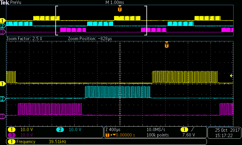
    I was able to implement that feedback circuit and verified that I could control the speed by adjusting the potentiometer as seen below by the duty cycle on the low side FETs.

    I noticed that while adjusting the speed the commutation frequency seemed to increase and decrease, is that correct? I was only expecting the duty cycle to adjust in order to alter the speed.

    Thanks for your help.

  • Hi HP,

    Yes it is expected to see commutation frequency to go higher. As the motor speed gets faster, we get less over all time for us to walk through 6 commutation cycle.


    Thanks,
    Seil
  • Seil,

    Does using the UC2625 in this voltage mode speed control mode change the behavior of the current limiting functionality with the isense pins? I ask because with a 0.05 ohm current sense resistor, I would expect a current limit of 4A (0.2V / Rsense) yet I seem to stall out my motor around 1A, well under my expected current draw. I noticed that the current sense signal is fed into the same OR gate as the output of the PWM op-amp as seen below.

    Can you provide any insight?

    Thank you

  • Hi HP,

    My thought on this is that speed loop is regulating the output motor voltage hence current is not going over 1A. You can change the external components for error amplifier to change speed loop dynamic and see current level is changing.

    Thanks,
    Seil
  • Seil,

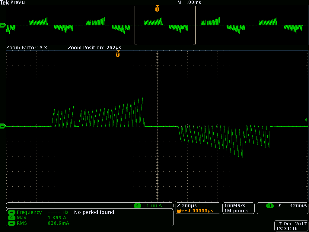
    I realized that I was measuring the current output from the power supply that was showing 1A. When I measure the current of a single phase, I see the following under no load:

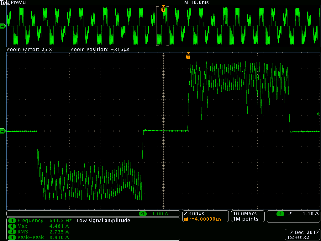
    This is under a high load in which I can see the ~4A limit taking effect.:

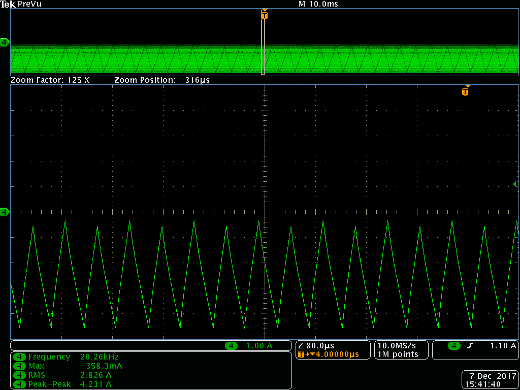
    Finally, this is under a stall condition with the one phase on:

    Do these phase current plots look ok to you? This may be a more general brushless DC question but I'm not sure what to expect. I would think that the current limit would be more like a flat line around 4A? Also, I'm confused why my power supply output shows less than 1A being drawn when the motor is actually pulling up to 4A?

    I appreciate your help.

    Thanks!

  • HP,

    The behavior you are seeing is correct. Motor driver is using PWM system hence you can't directly compare supply current vs motor winding current.

    For example, if you are drawing out 1A from 12V supply.
    you should expect 2A for winding current if PWM duty cycle is 50%. (2A* 12V*50% is the same as output power)

    yes. no load vs load will results in different current and different duty cycle.

    Thanks,
    Seil

    Please create a new thread. If you have additional question.