This thread has been locked.

If you have a related question, please click the "Ask a related question" button in the top right corner. The newly created question will be automatically linked to this question.

DRV8711: need help to plot winding current

Part Number: DRV8711
Other Parts Discussed in Thread: DRV8886AT, DRV8880, ,

Hi ,

1) Where should I connect my Oscilloscope probe to get the wave foam for winding current ?

2) I am not getting a smooth and fine wave foam when connect to the sensing resistor pads , why?

3) Is the current probe is must for doing the motor tuning?

I am using the Oscilloscope -RIGOL 1052E  and the china stepper motor( I=1A ,R=6.6ohm, L=8.2mH) DPM57SH51-1A.

Please help.

  • Hi Biju,

    1) Where should I connect my Oscilloscope probe to get the wave foam for winding current ?

    If you have a current probe, the probe should be connected to the AOUT1 wire running to the motor.
    If you do not have a current probe, a voltage probe can be connected to the AINSENP node. The voltage at this node can be converted into current. In addition it is best to have scope probes on both AOUT1 and AOUT2 to interpret how the current is being controlled (Drive, fast or slow decay)

    2) I am not getting a smooth and fine wave foam when connect to the sensing resistor pads , why?

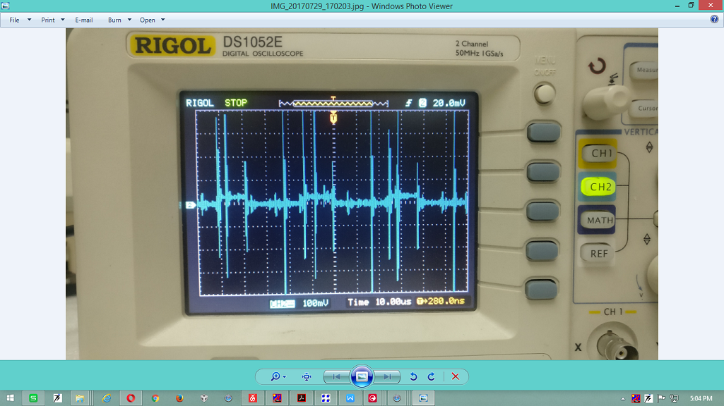
    Can you provide a scope capture? Typically you will not see a smooth waveform at the sense resistor. Please refer to figure 9 of the datasheet. The current during drive mode creates a positive voltage. The current during fast decay creates a negative voltage. The current during slow decay should create a voltage approaching zero because the current is recirculating.

    3) Is the current probe is must for doing the motor tuning?

    A current probe is not required. The current probe is ideal for interpreting the results.

    What are your register settings and sense resistor value?
  • Hi Rick,

    Thanks for the Quick reply.

    I am doing all the trial on your BOOSTER PACK DRV8711 board  by replacing the launch pad with a LOW COST micro controller. The motor is rotating fine but I need the wave form for tuning different motors.

    I have connected VINT pin directly to SLEEPn to enable the device automatically on power up.

    I don't have a current probe, so connected the scope voltage probe across the sense resistor (.05R) node, which is connected to BINSENP pin .  Please see the capture image taken when the motor run in low speed (12 pulse/sec) in FULL STEP.

    I have not changed any register from its default value except the two

    TORQUE Reg=0x0110

    CTRLreg =0x0C01

    I can take the capture by connecting to the  pin "AINSENP" . should I send the capture for AINSENP?.

  • Hi Biju,

    How many motors are you trying to tune? What is your system voltage and the current range of the motors?

    We have other devices such as the DRV8880 and DRV8886AT that may be better options. EVMS are available for both, and an external mcu can be used to control the devices.

    It is difficult to interpret the current information without the voltage information of AOUT1 and AOUT2. And seeing that you have a two channel scope instead of 4, this will be difficult.
  • Hi Rick,

    Its already working fine so why should I change the device? The MCU (ATmTiny24A) integration consumes less than 2 or 3 mA current from V5 pin. I will modify the VINT pin connection  with a voltage divider and zener circuit later .  The suggested replacement devices(DRV8880,8886AT) are not suitable for our application area, especially the current range .

    I just want to see the winding current  of the stepper ( current (I)=1A ,Resistance (R)=6.6ohm, Inductance(L)=8.2mH) DPM57SH51-1A  right now. The supply voltage is 24V.

    . So I request your help for this device. Should I send the voltages from AOUT1 and AOUT2  using a separate SCOPE?

  • Hi Rick ,

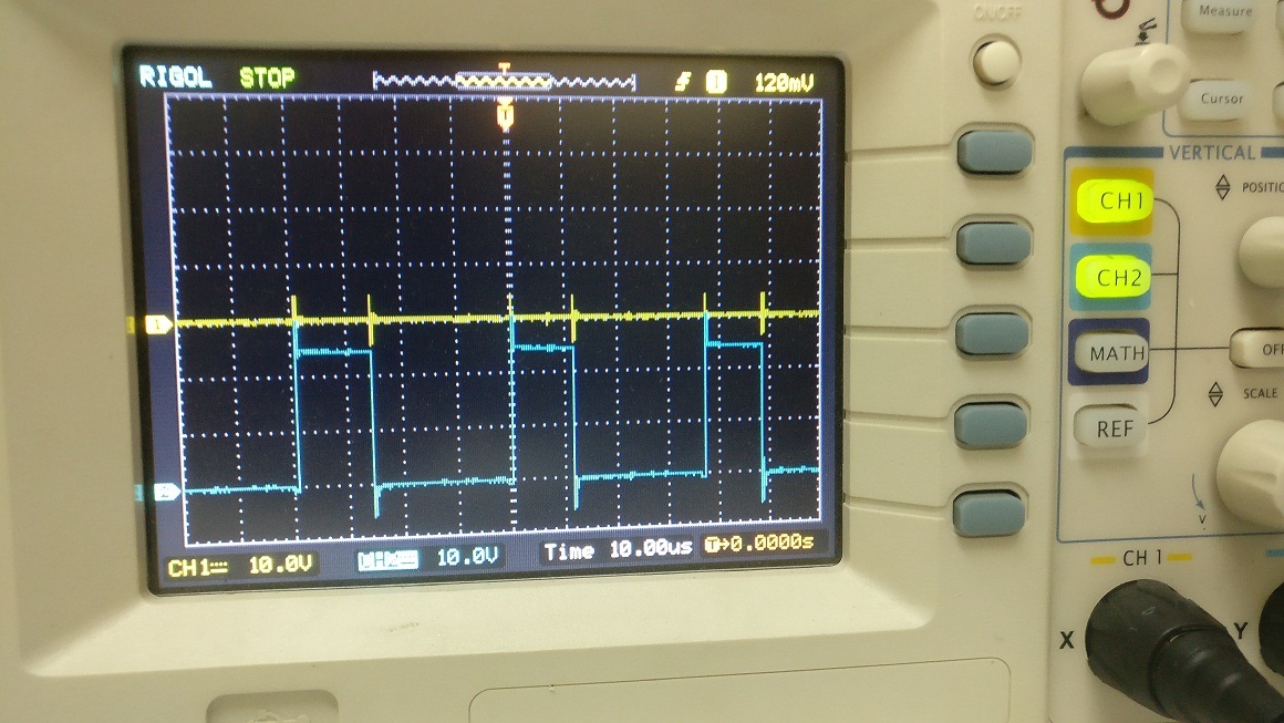
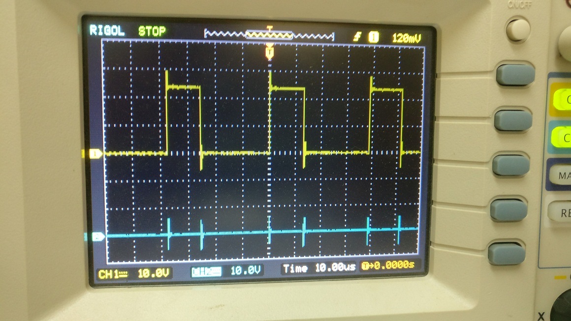
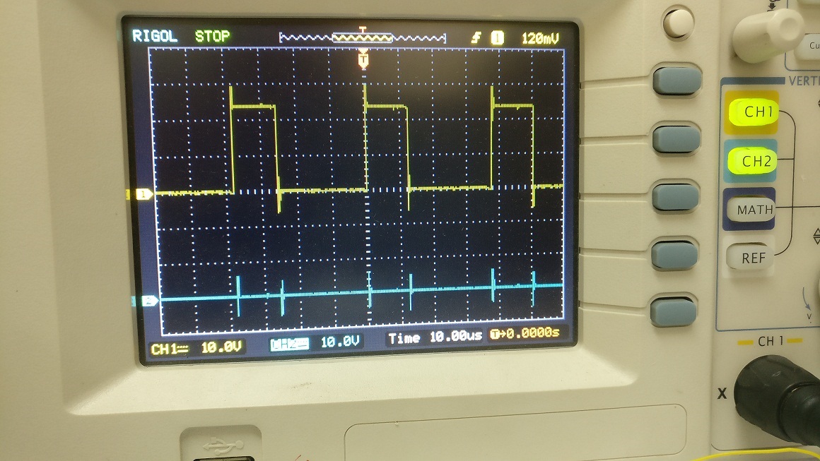
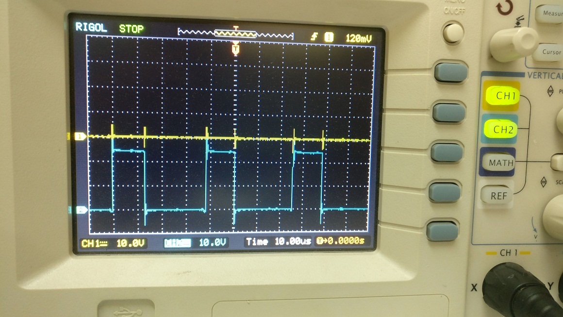
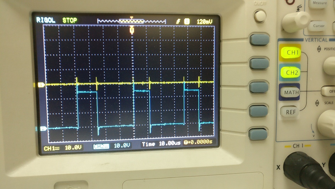
    Please see the AOUT1& AOUT2 scope captures in chanel1 ,Chanel2

  • Hi Biju,

    I suggested the other devices because they can reduce the system cost if your current and voltage needs are met. The devices have integrated FETs. I understand now you have higher current demands which are pushing you to the DRV8711.

    Thank you for the scope captures. This shows that you are regulating in slow decay, but does not show the current. The current can be calculated when Channel 1 is high and Channel 2 is low, or when Channel 2 is high and Channel 1 is low. The voltage across the resistor divided by the resistance provides the current value. Once both output are low, there is no current information.

    If you can gain access to a current probe, you will find it much easier to measure the current.

  • Hi Rick,

    You are right .It is difficult to measure the voltage at the sense resistor using scope, but I tried using a volt meter and  it shows 8.4mv at all the full step positions.

    An ammeter in series shows the winding current as  0.53A.  But I set the Toque reg for .48431(IFS=0.6821A) Is this  small difference is normal?

    Please not the modified Torque and CTRL values for the same.

    TORQUE=0x017F

    CTRL=0x0F01.

    I found one another issue related to home position . The winding current the is not as per the table explained in the data sheet. It start from zero at home position in 1/2 step mode.


  • Hi Rick,

    Busy for last few days, Can you find any solution from the supplied data in my earlier post? or should I buy a current probe to proceed?

    May I know the reason for the RESET position voltage changes?

    Awaiting your reply .Thanks in Advance.
  • Hi Biju,

    It would be best to obtain a current probe to proceed.

    What do you mean the current starts at 0 in half step? If after a reset pulse, this is normal. The outputs are disabled until the ENBL bit is written to a 1. At that point the current is correct.
  • Hi Rick,

    I will buy a current probe for this purpose. 

    The home position current is still  not showing correct even after writing 1 to the enable bit.

    According to the datasheet it should show the current 71% of IFS  at home position right? but the values are different in all modes 1/1,1/2,1/4,1/8. But  the current touches  100% value(.71A) If we continue the pulsing after home position. what may be the reason?

    I noticed a  small difference in my actual current and set current. I set the Toque reg for IFS=0.6821A (TORQUE=0x017F,CTRL=0x0F01.)  but I am getting the value .71A in my ammeter , Is this  difference is normal?

  • Hi Biju,

    I do not see the behavior you are seeing, but there could be a sequence difference. After the reset, I re-write all registers except CNTL while the STEP pin is low. While keeping the STEP pin low, the CNTL register is written to enable the device. At this point, I see 71% current in both windings as expected.

    What sequence do you use after the issuing the reset?
    Do you write to the RSTEP bit at the same time as the ENBL bit?
    Is the external STEP pin high?


    "I noticed a small difference in my actual current and set current. I set the Toque reg for IFS=0.6821A (TORQUE=0x017F,CTRL=0x0F01.) but I am getting the value .71A in my ammeter , Is this difference is normal?"

    Yes, this is normal. There can be some device to device variation.
  • Hi Rick,

    Thanks for the sequence. Its solved the home position problem.

    Few more doubts to be cleared

    1)Why we can not use VINT pin voltage for enabling the device on power up because its working this time Any consequences in future?

    2) Is the voltage divider -ZENER circuit for the SLEEPn pin connection is optional? Can you suggest any sample circuit suitable for the

    safe operation in the VM range 8 to 52V ?

    3) Even if Zener circuit is opted  can we design the board as sourcing  the power (approximately 3 mA current) from V5 pin to the MCU (ATmTiny24A) ?

  • Hi Biju,

    1)Why we can not use VINT pin voltage for enabling the device on power up because its working this time Any consequences in future?

    VINT is intended for internal use only.  SLEEPn has an internal pulldown which can consume 70uA.

    2) Is the voltage divider -ZENER circuit for the SLEEPn pin connection is optional? Can you suggest any sample circuit suitable for the

    safe operation in the VM range 8 to 52V ?

    The problem with a voltage divider - Zener is the possibility of the lower resistor opening. This will send the full VM voltage to the SLEEPn pin.

    You can connect V5 to SLEEPn instead of VINT or the voltage divider. V5 remains active.

    3) Even if Zener circuit is opted  can we design the board as sourcing  the power (approximately 3 mA current) from V5 pin to the MCU (ATmTiny24A) ?

    Yes, you can supply up to 10mA external load current. Please refer to the Recommended Operating Conditions in the datasheet.

  • Hi Rick,

    Thanks for clarifying the issues.

    "You can connect V5 to SLEEPn instead of VINT or the voltage divider. V5 remains active."

    Let me say that my plan is to design a drive with minimum external components. So a voltage regulator using only for start up the system is not brilliant.

    1)This V5 pin is only active(5V) when SLEEPn is High. It was better If the voltage at V5 pin comes on start-up. May I know why the voltage at V5 is missing on Startup?

    2)Is there any other way to get the voltage from V5 Pin on startup?

    3) I can not use MCU to trigger SLEEPn , because of the same issue  .A voltage source  is also required for the MCU. Can you suggest any Idea or circuit to solve this issue?

  • Hi Rick,
    My last post was very much crucial .Awaiting your advice to proceed.. .
  • Hi Biju,

    Sorry, you are correct. VINT is alive when the device is in sleep mode and V5 is not.

    Unfortunately, the low power mode disables the V5 regulator. Using VINT is a risk for a few reasons.
    1) It is designed for internal use only.
    2) There is not much noise margin available. Noise could cause the nSLEEP pin to disable the device.


    The original voltage divider from VM + zener works.
    Another option is to use some type of capacitor coupled actuator to control nSLEEP. Once nSLEEP is enabled, V5 can drive nSLEEP to keep the DRV8711 awake.
  • HI Rick,

    Thanks for the quick response. I choose a low cost linear regulator (ZXTR2105 )as a solution. Please correct me if I am wrong.

    I am going to replace all the connections to the new IC output from V5 and nSLEEP, then VINT can be made free  as your wish.

    1) Should I care any thing for making both the ground common.?

    2) Any design rules should be followed for the ground layer of the PCB?

  • Hi Biju,

    The regulator will work. Thank you for removing the connection to VINT.

    1) Should I care any thing for making both the ground common.?

    Can you clarify? The grounds should be connected to avoid voltage mismatches.

    2) Any design rules should be followed for the ground layer of the PCB?

    Please see the DRV8711EVM or the BOOST-DRV8711 for examples of layout. The layouts are available on line.
  • Hi Rick,

    Thanks for confirming the regulator working. Leave the question about ground layer , I will follow the layout examples from the data sheet.

     I am awaiting a DC clamp meter ,which can be connected to the SCOPE for plotting the winding current. Still one key issue is pending to be solved regarding micro-stepping

    1)In 256-micro stepping mode I have noticed motor shaft jumping( or skipping) of multiple positions  when giving single pulses to the STEP input.  We can discuss this matter in detail after receiving my DC ammeter.  So that I can submit more data s for your reference ,but  May I know this can be solved by proper tuning?

    2).I am only concentrating on stepper-motors. I have a confusion for choosing the proper method for rotating the  motor .I found two options in the data sheet and both are equally fine for my application.

    a) Give the  pulses to the STEP pin

    b) Writing 1 to RSTEP of the CTRL register.

    Can you share some points as a comparison of these methods.?

    May I know that the limit for maximum Step frequency( 250khz ) is also same in Second Method(b)?

    Is it possible to cross this limit through SPI interface?


  • Hi Biju,

    1)In 256-micro stepping mode I have noticed motor shaft jumping( or skipping) of multiple positions when giving single pulses to the STEP input. We can discuss this matter in detail after receiving my DC ammeter. So that I can submit more data s for your reference ,but May I know this can be solved by proper tuning?

    Can you describe this jumping in more detail? Is the motor moving more than one full step when this occurs?

    2) Either STEP or RSTEP work
    a) The STEP pin allows the PWM timer to control the indexer directly. This makes motor control (accel, speed, decel) easier to implement, but cost a GPIO on the mcu.
    b) The RSTEP bit saves a GPIO but is more difficult to time properly. This is especially true if there are multiple SPI devices used.

    It is not possible to cross the maximum step frequency limit using the SPI. The limit is the same.
  • Hi Rick,

    Thanks again for the quick response.

    Let me to explain my testing procedure in detail for the 256-microstepping issue.

    I have given the  frequency of 1Hz to the STEP pin.After then holding the motor shaft(Zero load) with my fingers , I can  feel the steps, but its not uniform.

    Some time the fingers not feel the steps and soon after this it rotates the missed steps all together on next pulse. I think the rotation unit may be in

    micro-step angle=  1.8degree/256 =0.00703125 degree, but some times it executes multiples of the micro-step angle together. 

    I have to set up a laser reflection arrangement to measure the jumping angle more accurately. Hoping that you may understood the issue. May I know this can be solved by proper tuning?

  • Hi Biju,

    My understanding is that accuracy of the stepper motor is only correct at full step locations. The torque change between 1 microstep to the next is very small. The motor may not be able to overcome the load. Some type of gear may be required to achieve your goal.

    Please consult with your motor manufacturer to confirm.
  • Hi Rick,

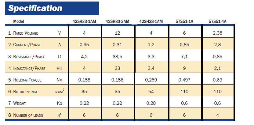
    Thanks for the reply . Unfortunately I am very much disappointed on your answer,because the drive board is mainly for positioning purpose rather than smooth rotation. I can understand the current difference you are saying ,but I am expecting a 1/256 resolution movement at least in zero load. Full step accuracy is not sufficient for us. We already  have a 1/16 micro-step drive, which is working fine .  If the positioning accuracy is depending on motor specification,  you can suggest the same type of motor for the testing.Please see the list of different motors we are using ..