This thread has been locked.

If you have a related question, please click the "Ask a related question" button in the top right corner. The newly created question will be automatically linked to this question.

DRV8871EVM: I have an issue with 1Mhz chopping of output

Part Number: DRV8871EVM
Other Parts Discussed in Thread: DRV8871

Hi,

I have a DRV8871 Evaluation board and I am using external PWM and was wondering if the full 0% to 100% duty cycle range can be used if the PWM frequency is 100khz.

The reason I ask this is to know whether or not the internal charge pump has any special requirements.


Also: 

I am using a sinusoidal PWM, with INA1 set high and sinusoidally pulsing the INA2 for the positive half cycle and INA2 set high and sinusoidally pulsing INA1 for the negative half cycle.

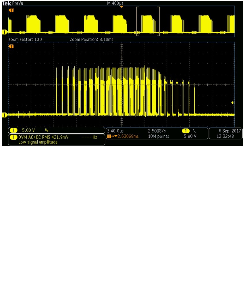
I am seeing a 1Mhz chopping of the output current for part of the negative cycle, and was wondering where this originates from, I don't think it is the current limit as the current is only +/- 0.25Amp.


Any thoughts welcome,


Kind Regards,


Conor.

  • Hi,

    Please see two scope traces below, the first one is zoomed in on out1, the second one is zoomed in on the 1Mhz detail.


  •  Sorry the second image was a duplicate of the first, here is the correct one:

  • Hi Conor,

    Can you provide the input signals for reference?

    There is a minimum 800ns pulse width for the input (footnote 1 of Recommended Operating Conditions). This limits the duty cycle at 100kHz to 8 to 92%.
  • Hi Rick,

    The first image is a zoomed out version showing the overall picture of what is happening

    The second image is showing sinusoidal pulsing on IN1 (yellow) and it resultant output (green)

    The third image is showing sinusoidal pulsing on IN2 (blue) and it resultant output (purple)

    The fourth image  is zoomed in version of third image.

    The fifth image is a zoomed in version of the fourth image.

    The noise on the IN2 (blue) signal is coupled from the output, in other words the output from the micro controller is clean.

    Also it is possible to kill the noise by adjusting the supply voltage up and down back to the original level,

    but all of a sudden this phenomenon returns and stays until cycling the supply voltage again.

    Kind Regards,

    Conor.

  • Hi Conor,

    Can you re-capture the images with a couple of changes:
    1) Please change channel 2 to DC
    2) The noise only appears when OUT2 is toggling. Can you look into the reason for this?

    At this point, I can only comment on the second image. Assuming IN2 is high, the outputs are operating as expected.

    Once the channels are DC based and hopefully the noise is cleared up, I can comment more.
  • Hi Rick,

    Simply putting a capacitor between IN1, IN2 to ground fixed the problem, so it does look like it was the feedback coupling

    from the output that caused the problem after all.

    It would still be interesting to know if there is any significance in the 1Mhz.  Is there any circuits in the chip that operate at 1Mhz.

    See clean waveforms below!

    Kind Regards,

    Conor.

  • Hi Conor,

    Thanks for the updated waveforms.

    The previous waveforms showed signals that could have been violating the absolute maximum and minimum voltages. Because of that, it is difficult to speculate on the cause of the 1MHz.
  • Hi Rick,

    I am still having some issues and wondering if you can explain how 100% duty cycle can work?

    I would have thought that at static condition (100% duty cycle) that the bootstrap power supply would stop working.

    This in turn would mean that the high side FET driver would no longer work.

    Yet it mentions 100% duty cycle in a few p[laces in the data sheet.

    Kind Regards,

    Conor. 

  • Hi Conor,

    The DRV8871 has an internal charge pump to provide the voltage/current need to drive the high side FET at 100% duty cycle. Please refer to section 7.2 for details.