This thread has been locked.

If you have a related question, please click the "Ask a related question" button in the top right corner. The newly created question will be automatically linked to this question.

DRV8884: RMS current measured is not as expected

Part Number: DRV8884

Hi,

The current input to the motor is measured as 60mA, but the design value is 75mA. What could have caused this change?

Please see the details..

1. RREF = 562K

2. TRQ = 1

3. DECAY = tied to DVDD (slow decay)

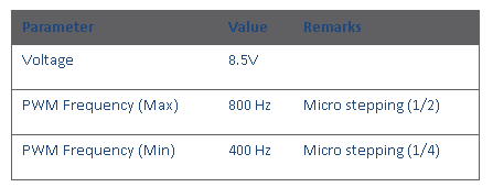
4. We use both 1/4 and 1/2 stepping modes in our design and two PWM frequency - 400Hz and 800Hz.

5. Motor current waveform is shown below.

  • Hi uhtis,

    Thank you for the information.

    Using a 562k RREF resistor should result in 53mA max current when the motor is running (37.7mA RMS).

    The current image is appears to be close to this, although there may be some error in the 562k resistor, the DRV8884, and the probe.

    What value would you like to see at the peak of the current? Assuming you want 75mA, the RREF resistor value should be 400kOhm.
  • We need 75mA rms current , so 106mA full scale current. With these the resistor would be 282K. Please confirm. And also, how much can be the tolerance? 

  • Hi Uhtis,

    It is recommended to use ~141k resistor with a torque setting of 50%.

    This should provide optimal performance at such low currents. Using the torque setting of 50% reduces the blanking time to 1us instead of the standard 1.5us, which should help with current ripple. Please refer to table 6 for details.