This thread has been locked.

If you have a related question, please click the "Ask a related question" button in the top right corner. The newly created question will be automatically linked to this question.

DRV120: PWM Frequency setting not working

Part Number: DRV120
Other Parts Discussed in Thread: TINA-TI

I have a similar problem as in earlier post on this forum:  "DRV120 ROSC resistor change" (e2e.ti.com/support/applications/motor_drivers/f/38/t/529326 ), Unfortunately the discussion turns private in the end so there is no solution available...

Anyway, I'm driving a 24V 100mH solenoid that requires 170mA start current and 85mA hold current with DRV120 but I can't get it working so that it wouldn't sound very annoying. I have tried multiple different resistor values for all the peak, hold and osc settings without getting it work properly. Sometimes the PWM turns very unstable and sometimes it's a lot lower than it is supposed to be. For example with 180k Rosc the frequency should be according to datasheet over 22kHz but it actually is when measured 10,5kHz (Other settings Rhold 68k and Rpeak 68k).

Any idea what is causing this?

  • Hi Petteri,

    I can assist you with this issue.

    First, can you send me the DRV120 portion of your schematic as well as screenshots of the voltage at the output node and current through the inductor?

    Regards,
    Kevin

  • Hi Kevin,

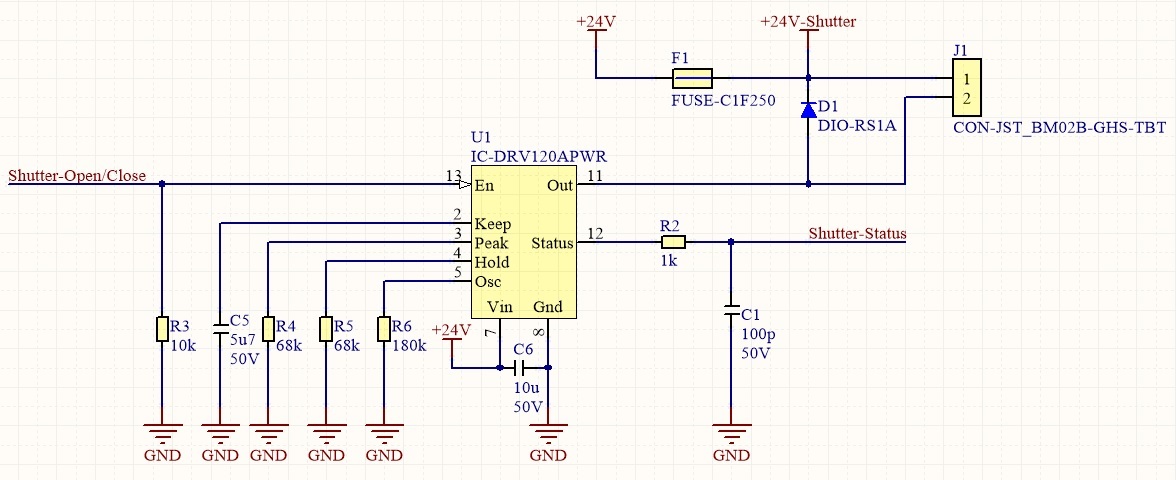
    Thank you! Here are the schematics. The solenoid is connected to the connector with about 50cm long AWG26 wires.

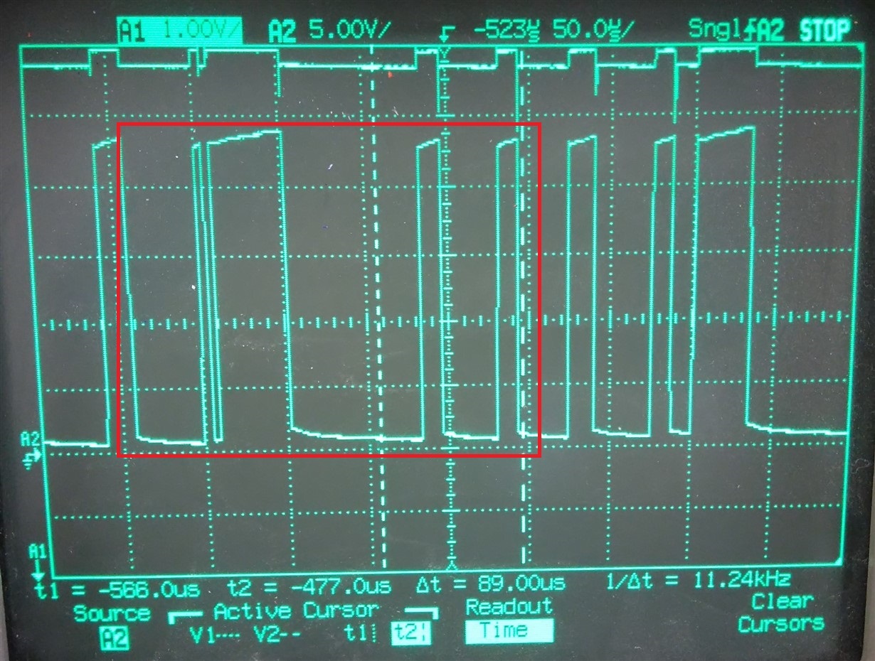
    Below is a few pictures of the unstable signals on both sides of the D1 diode. Actually last time that I tried the same setup with same component values it worked with stable 10,5kHz PWM. Unfortunately I wasn't able to measure the current with oscilloscope so I had to use a multimeter in series. The result was that the current varied around 88-91mA.

    I had to use a very old oscilloscope for the measurements as our better one has only active probes but hopefully those tell you enough of the problem.

    Any idea what could I do to fix the problem?

    Best regards,

    Petteri

  • Petteri,

    Thank you for posting those screenshots. A couple questions:

    1. Are both the first and second picture the output signal with Rosc = 180k?
    2. On a somewhat unrelated topic, in your original post you said your solenoid needs a start current of 170mA and a hold current of 85mA. With your Rpeak and Rhold values you will have a peak current of 245mA and a hold current of around 98mA. Just wanted to check that you want that much margin.

    Without seeing the current waveform on the oscilloscope I can't say for sure but I have a good idea of the problem. The DRV120 can only sense current while the FET gate is closed. Imagine there is a clk signal at the same frequency as fpwm. At the start of every clk cycle the gate is closed for at least a minimum duty cycle of 8%. At that time it senses the current and makes a decision, based on a hysteresis window, whether the current is low enough to keep the gate closed or open it and let the current decrease more. What happens to cause that "unstable" PWM signal is the PWM frequency is set too fast for the current to drain all the way outside of the hysteresis window while the gate is open every time. So here's an example of what is happening:

    1. Gate is closed, current ramps up to peak value.
    2. Current hits peak value, gate opens (when this happens it is going to stay open until the next clk cycle and no current is sensed). We'll say that it hit the peak value 60% through the cycle so it had a 60% duty cycle.
    3. Next clk cycle the gate is closed and it sees the current isn't low enough (but imagine it's close) so it stays closed for a minimum 8% duty cycle then opens the rest of the clk cycle.
    4. Next clk cycle the gate is closed, current is sensed. Now the current has dropped pretty far from the peak, far enough so that for it to get back to it's peak value it has to stay closed for nearly two whole clk cycles. 
    5. Then maybe it goes back to a more uniform signal at the correct frequency for a little bit

    When this happens you end up seeing a PWM signal that doesn't look uniform. In the example I gave, you would've seen a 60% duty cycle, then 8%, then 100% which is very non-uniform, and since you saw it high for almost two clk cycles it looks slower than the frequency you expect sometimes. Internally it is still making decisions at the fpwm that you set but the PWM may not actually look like that frequency. The example I gave is similar to what you're seeing in your second picture (added at the bottom and highlighted). Keep in mind the gate voltage will be opposite of the voltage you're seeing on the scope.

    Two possible solutions:

    • Try a solenoid that has lower inductance. This will allow current to ramp faster and get outside of the window during a clk cycle 100% of the time.
    • Lower the set frequency by increasing Rosc. Based on your original post it sounded like you wanted to stay out of the audible band so that may not be a viable option.

  • Thank you Kevin!

    Answers to your questions:

    1. Yes. Every picture was with the same component values

    2. The reason for this was that I wanted to try if these problems had something to do with too low driving currents but they didn't have any effect. I will change them back to lower currents when we find a solution to the problem.


    Your solution to use lower inductance solenoid confuses me because in the datasheet it says that the recommended nominal inductance for the solenoid is 1H and there is no limits for the minimun and maximum values. Also the driver is not driving the solenoid with PWM that I set with the resistor. For example I changed the Rosc to 220k and the PWM stabilized to constant 9kHz but according to the datasheet that should mean about 18kHz PWM. Is there mistakes in the datasheet or what could be the reason for this?

  • If possible, can you retake your most recent screenshot and measure duty cycle? When I estimate I get right around 42%. What that would mean to me is you are seeing the same issue I described in my long reply, but more difficult to spot. Keep in mind the start of a cycle, when looking at the DRV120 OUT pin, will never be on a rising edge. It will be on a falling edge or somewhere during a low period, if it takes more than one cycle to reach peak current, because at the start of a cycle the DRV120 always needs to pull the FET gate high (low on OUT pin) to check the current. So imagine the start of a cycle is at the falling edge after your cursor in your screenshot. What it looks like is the FET gate is pulled high for a full cycle (low on the o-scope shot) then on the next cycle the FET gate stays high for 8% (or some value close to the minimum on time) then goes low for the rest. So those two cycles are looking like one long cycle, effectively halving the frequency. 

    I replicated the issue, but more drastically, by changing up the TINA-TI Reference Design in the DRV120 product folder to help explain. Pictures and explanation below:

    In my simulation Rosc = 180k. So fpwm is around 22kHz, meaning the period is close to 45us. The top graph is Vout of the DRV120, AM1 is the current through the solenoid. Notice how consistent the voltage PWM is, but it looks to be running at a third of the set frequency. If you look at the first picture, in the cycle (a-b) the voltage is low for a short time and then goes high, once it hits the peak current value, to let current drain. This took 45us, or one cycle, if you look in the top right. Then once the voltage goes low again, to increase current, it takes two cycles (90us) of 100% duty cycle, on the FET gate, to get back to the same point. So, in effect, the frequency was just cut to a third of it's set value (three cycles to drain and then reach peak instead of one).

    In regards to me saying lower the inductance and the datasheet recommendation. You are right, you can use an inductance value of your choice. What I should have made more clear is the unstable PWM is not really a problem; the part is functioning correctly. If you want the FET gate PWM to look stable and at the frequency you set with Rosc, the current in the inductor has to be able to rise to the peak and fall outside the hysteresis window within one cycle. When your inductance gets too high the current can't ramp up fast enough and it could start taking more than one cycle to ramp. But, again, this isn't a problem. The part is regulating current the way it is meant. So at the frequency you choose you may see that unstable PWM phenomenon in the picture I used in my last reply or what you are seeing in your most recent picture.That's why I recommended lower the inductance. The part itself is making decisions at the frequency you set but to regulate the current it may have to take more than one cycle.

    If I take the same file that I was using for my simulation example above and decrease the inductance the part starts working as you expect:

    Now within 45us the current is rising to the peak and falling out of that window; the PWM looks to be at 22kHz.

    Hope that helps,

    Kevin