This thread has been locked.

If you have a related question, please click the "Ask a related question" button in the top right corner. The newly created question will be automatically linked to this question.

DRV110: DRV110 External Component Selection

Part Number: DRV110

I am having problems determining the external values for a DRV110 application. 

I am trying to control a DC solenoid for a valve.  The solenoid is rated for 7 watts @ 24V.  Measuring the coil with a meter indicates approximately 87 ohms.  

I am using a 1 ohm sense resistor and powering device from the same +24V supply which drives the solenoid.   I am using the same FET as used in your reference design, STD1NK60, in a DPAK.

My first issue is with determining the series resistor for the supply voltage to the DRV110.  I currently have a 1K resistor, however, I see ripple on the VIN pin of the device when the device is in the hold mode.  Is this ok?

For testing purposes, I went with the default values of ipeak and ihold by using 0 ohm resistors at rpeak and rhold.  When I enable the device, I here the solenoid engage, and the DRV110 switches over to the hold mode.  The solenoid remains engaged, but if I look at the gate of the FET, I see a somewhat erratic waveform.  I would of expected to see a waveform with a well define duty cycle, but I do not.  The duty cycle is constantly changing with no apparent pattern.  Is this normal?

I read in some other threads that there is a spreadsheet available for helping determine the proper values for this device.  How do I obtain this spreadsheet. 

Thank you, Jim

  • Jim,

    1) Use Equation 5 (in section 7.3.5) of the datasheet to determine Rs. For 24V I would expect an Rs between 1k-9k. You can also test out different Rs values to see how your design performs. Ripple on input is normal. How much ripple are you seeing?

    2) A non-uniform PWM is normal under certain circumstances. It is key to look at the current of the solenoid though. The part is keeping the current at the level you are setting but to do that it may have to vary the PWM duty cycle. I'll point you a different post where another person saw two different strange phenomenon that are actually the part working properly. I go into the full explanation in my second and third response (e2e.ti.com/support/applications/motor_drivers/f/38/t/641857) . Short answer is that yes it is normal. To see a stable PWM signal on the gate, at the frequency you set, the current through the solenoid has to rise to the set value and then fall out of the hysteresis window in one cycle. When fpwm is running faster than that it may have to vary the duty cycle to keep the current where it is set because of how it checks the current.

    Finally, the spreadsheet you mentioned is attached. Use the "DRV110 Zener" sheet to help determine Rs and "DRV110 Passives" to help select Rhold, Rpeak, etc.

    DRV1xx Device Parameter Selector.xlsx

  • Jim,

    I wanted to make a correction to my last post...I originally said I would expect an Rs between 1k and 9k but at the minimum I would expect 3k. You dont want to supply the part more than 3mA so to get your Rs(min) you use Rs(min) = (Vs-15)/3mA = 3k. Any smaller resistance than that and you may start to see problems with the part.

    Regards,
    Kevin
  • Hi Kevin,

    Per your recommendation, I increased the Rs resistor to 6.81K.

    When enabled,  I am seeing a sawtooth waveform with approximately 700mV peak to peak on the DRV110 side of this resistor.  The period of this waveform is about 6 KHz.  The supply side of this resistor is clean with no ripple.

    I have the board configured with 0 ohm resistors for Rpeak, Rhold and Rosc and 2uF for Ckeep. 

    With a 1 ohm resistor for Rsense, per the datasheet I should expect  300 mA for Ipeak and 50 mA for Ihold.  I do here a click when I enable the DRV110, but I am not seeing 50mA of hold current.  According to my meter which I have in series with the supply, I only see additional 10mA of current in the hold state.  This is not enough current to keep the solenoid engaged which I have verified as the valve which is controlled by the solenoid does not remain closed.

    The FET gate still has a varying duty cycle waveform with a period of approximately 20 KHz.

    I can try and capture some waveforms if that would be helpful.  Just let me know what you would like to see.

    Regards, Jim

  • Jim,

    Can you try moving your meter so that it is in series with the solenoid (between the solenoid and high side of the FET)? I have the EVM setup for an Ihold = 150mA with an Rsense of 1ohm. When I measure with the multimeter in series with the supply I measure 20.7mA, when it is in series with the solenoid and high side of the FET I measure 152mA. If you still see 10mA I'll dig deeper but that sounds normal with where you said you are measuring.

    It sounds like the problem you are seeing is that 50mA isn't enough to keep the solenoid held. You could try putting an Rhold of 55k-66.67k just see if it's held open with more current. That will change Ihold to 150mA.


    Regards,
    Kevin

  • Kevin-

    I moved the meter as you suggested and the current reading is as expected with a 0 ohm resistor. I was reading about 47.5 mA. I changed Rhold to 100K and the valve seems to be working correctly. The gate signal is vary erratic looking with all kinds of varying duty cycles, but it appears to be functioning.

    One other thing that a younger colleague noticed because I could not hear it, is that when the DRV100 is enabled, you can hear the 20 KHz PWM signal. Is there anything that can be done to reduce this? I guess we could change the PWM frequency and see if we can find one that is less noticeable.

    Regards,
    Jim
  • Jim,

    Happy to hear that increasing Rhold is helping it function more expectedly.

    1) The gate signal having a varying duty cycle is usually okay. I would recommend looking at the current through the solenoid on an o-scope, if possible, to see if there is a lot of ringing when the FET switches. If there is ringing it could be causing the sense comparator to falsely trip. My recommendation for that is farther down in my response.

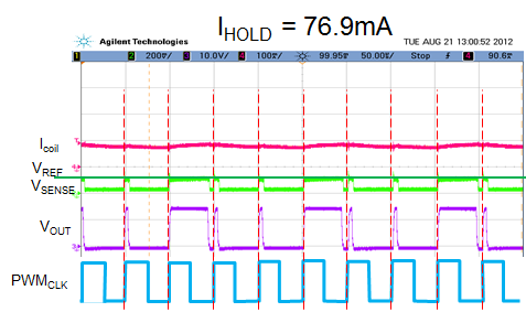
    If you don't see ringing you usually see varying duty cycle when the current doesn't rise and fall to the same point in one cycle. A constant duty cycle means the current is rising to the peak and then falling out of the hysteresis window in one cycle. If you are looking at the FET gate, during the high period it rises to the peak and then when it's low the current falls out of the window to the same point every time. When you see a varying duty cycle the current isn't rising and falling to the same point. Usually the way it goes is:

    1. FET Gate high, current reaches peak.
    2. FET gate goes low, now no current can be sensed, current drops close to the outside of the window.
    3. Next cycle FET gate high to sense current. It turns on for minimum 8%. The current rises a little bit while it's on, but it sees the current isn't outside of the window so it shuts off for the rest of the cycle.
    4. Next cycle the FET turns on and sees that the current is far outside the window so the FET gate stays high for close to 90% duty cycle or even multiple periods.

    An example of this sort of behavior is below:

    This one is pretty uniform with one period high for a long time then two minimum on-time periods on the FET gate (Vout). But this is the sort of thing you can see. The first cycle the current is high enough so the FET stays high for its minimum on time then shuts off the rest of the period. Next cycle it turns on to check the current and sees that it still isn't low enough so it stays on for its minimum on time and then shuts off the rest of the period. Next cycle the gate goes high and the sense pin sees that the current has gone outside the window. It has to stay on for ~90% to get back to its set point, then this whole thing repeats. The FET gate looks a little strange with the varying duty cycle, but the current through the coil is fine. It's just the part doing its best to regulate the current. To do that it may have to vary the duty cycle.

    2) A few things we usually recommend to reduce audible noise.

    1. You can try to increase the frequency. That could take it out of the audible range. 
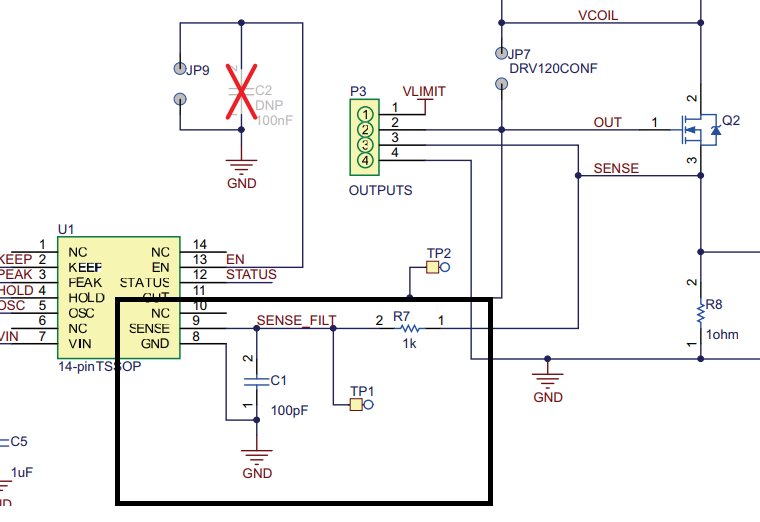
    2. Next you can add a filter between the sense resistor and the sense pin. Do you already have that there? This could also help your strange duty cycle. Another way the strange duty cycle can be caused is by ringing on the sense resistor from the switching of the FET. Sometimes the ringing is bad enough to trip the sense pin comparator before it reaches the peak. What we recommend, and what we use on the EVM, is a 1k resistor and 100pF capacitor. If that isn't enough you can increase the capacitance.

    Regards,

    Kevin

  • Hi Kevin-

    The example waveform in your last email is very similar to what I am seeing although the longer cycles are not quite as uniform as depicted.  I see the minimum cycles followed by longer cycles of varying on times.  As you mentioned, I guess it is the device trying to do the best it can to regulate the current.

    I already have the 1K/100pF RC filter you mentioned on my board.   I have not changed any of the values.

    To measure solenoid current using your oscilloscope, did you use some type of a current probe? 

    Thanks,

    Jim

  • Jim,

    I have a Tektronix A6302 current probe on the wire between the solenoid and high side of the FET into a Tektronix AM503B current probe amplifier into my oscilloscope.

    Regards,
    Kevin