This thread has been locked.

If you have a related question, please click the "Ask a related question" button in the top right corner. The newly created question will be automatically linked to this question.

DRV110: Setting IPeak and IHold with a FET Mux/Demux

Part Number: DRV110
Other Parts Discussed in Thread: SN74CB3Q3253

Hi,

Our plan is to set Ipeak and Ihold of the DRV110 with a SN74CB3Q3253 (Dual 1-of-4 FET Mux/Demux). This device is supplied with a 3.3V supply allowing switching voltage to be up to 5V. Therefore I have the following question:

How can I calculate the voltage at the HOLD and PEAK pins with a given resistor switched to those pins? I want to make shure that the voltage does not rise above the 5V limit of the switch.


A second question is about the calculation of the series resistor for the zener diode. In the datasheet there is equation 5 telling Rs is depending on VsmaxDC. If I look into the calculation spreadsheet for the DRV110 I can see that one parameter is "Vs,min (V)" to choose the resistor Rs. What is correct, datasheet or spreadsheet?

Thnaks and best regards,

Patrick

  • Hi Patrick,

    Thanks for coming to us with this!

    1) Are you worried about the voltage on the HOLD or PEAK pin being greater than 5V? If that is the case you should be fine without even measuring it. The part determines Ihold and Ipeak by supplying a constant 1V to the HOLD and PEAK pins and then measuring the current it is supplying to Rhold and Rpeak. So what you measure at the HOLD and PEAK pins will be 1V for Rhold/Rpeak greater than 66.67k(typ). Once you get to less than 66.67k(typ) you hit the current limit that can be supplied to Rhold/Rpeak and the voltage on those pins starts to droop. Since the current output to the PEAK/HOLD pins hits its peak at 66.67k you won't see an increase in Ihold/Ipeak for resistors less than 66.67k. So, in summary, you should be fine since you will see a max right near 1V on those pins. I have some data from a part to show what I am saying (Vpeak is the same over Rpeak):

    2) This is a helpful catch Patrick. For equation 5 I would actually recommend using Vs(min). Usually Vs(max) and Vs(min) are close enough to where it won't matter a whole lot, but in your case it may. That equation is setting your current floor so you should use your Vs floor (if you look in table 6.3 the min supply current recommended is 1mA which is used in that formula). If you used Vs(max) in that formula, any voltage less than Vs(max) will cause you to supply less than 1mA.

    A better way for you may be to get a range of resistors using two separate formulas. Use something like Rs(min) = (Vs(max)-15)/3mA and Rs(max) = (Vs(min)-15)/1mA. For instance, let's say you have Vs(max) = 18.5V, Vs(min) = 17.5V. Using the formulas I mentioned Rs(min) = 1.166k, Rs(max) = 2.5k. Lets say we choose Rs = 1.5k since it is in between there. We can back calculate the total current for that chosen resistor using I = (Vs-15)/Rs. Using that formula, Imax = (18.5-15)/1.5k = 2.33mA, Imin = (17.5-15)/1.5k = 1.66mA. By using those formulas we picked an Rs that keeps us between the recommended operating conditions for both Vs(max) and Vs(min).

    Only problem with the way I just mentioned is that if your Vs(max) and Vs(min) are very far apart, you may end up with an unusable range. But theyd have to be quite a bit more than 1V apart to see those formulas not work.

    Hope that helps!

    Kevin Schmidgall

  • Hi Kevin,

    Thanks for your detailed explanation. Yes, I was worried about the voltage level at HOLD and PEAK pins but now all is fine. Your explanation how this two pins work would be a good addition to the datasheet.

    For the second topic I'm in doubt what to do best. My Vs range is 18V...32V. So for the given quiescent current range of 1mA to 3mA there is no solution for a resistor. Any idea on how to solve that in a cheap way?

    I only see an additional external zener diode/resistor stage bus this is quite difficult with the current range of 1mA to 3mA. What is the current consumption of the DRV110 if I for example supply it with 12V (or a voltage less than 15V)? To this cutrrent I would add the average current for the gate charge (e.g. 0.3mA). This total current I would assume flows into DRV110 while staying below 15V.

    Thanks for your support,

    Best reagards,

    Patrick

  • Patrick,

    That's an interesting problem with such a wide range of input voltage. First thing that comes to mind is use a wide Vin buck regulator to regulate that wide range to just one voltage. Possibly regulate it down to 16V or even less than 15V. Then no matter what it is, 18-32V, the solenoid and DRV110 and solenoid will always see that one voltage.

    With your last paragraph are you trying to get at what the current draw of the DRV110 is when the zener hasn't clamped so you can figure out what the absolute minimum current you could allow in to have the DRV110 function is? When putting a multimeter in series with Vin = 12V the average current I measure is 450uA with a solenoid as the load, and 330uA with no load. I wouldn't recommend trying to go for the absolute minimum though. With variation in your current limiting resistor and current draw from part to part you could be getting into unexpected operation range. If you used the formulas I gave above you get an Rs(min) of 5.667k. If I try using that with 18V I get an Iin = (18-15)/5.667k = 529uA. So at 32V you'll allow in 3mA and at 18V you'll allow in 529uA. You can test with that and decide if that is enough margin for you, but you are outside the recommended operating range so I would check everything (Vin is clamped near 15V, current is regulated where you expect, etc.).

    Regards,
    Kevin
  • Kevin,

    Thanks for your support.

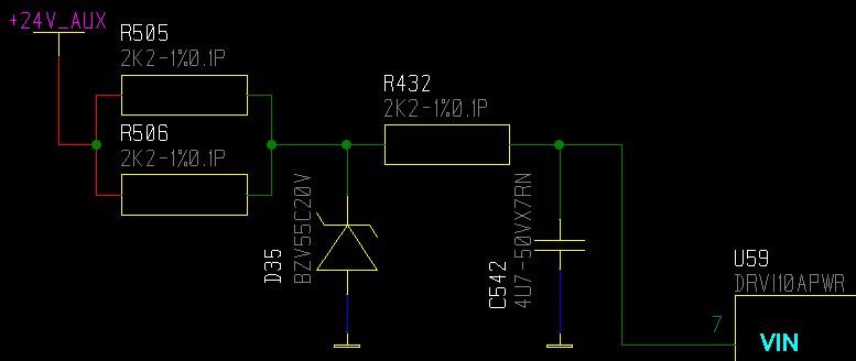
    I will try with an external resistor/zener stage (please see picture). With 18V I'm slightly violating the 1mA current specification.

    Regards,

    Patrick