This thread has been locked.

If you have a related question, please click the "Ask a related question" button in the top right corner. The newly created question will be automatically linked to this question.

DRV8302: Brushless Sensorless Motor speed oscillates, which causes it to lose sync and shut off once it goes too fast.

Part Number: DRV8302

Hello motor control gurus. I am not one of you.

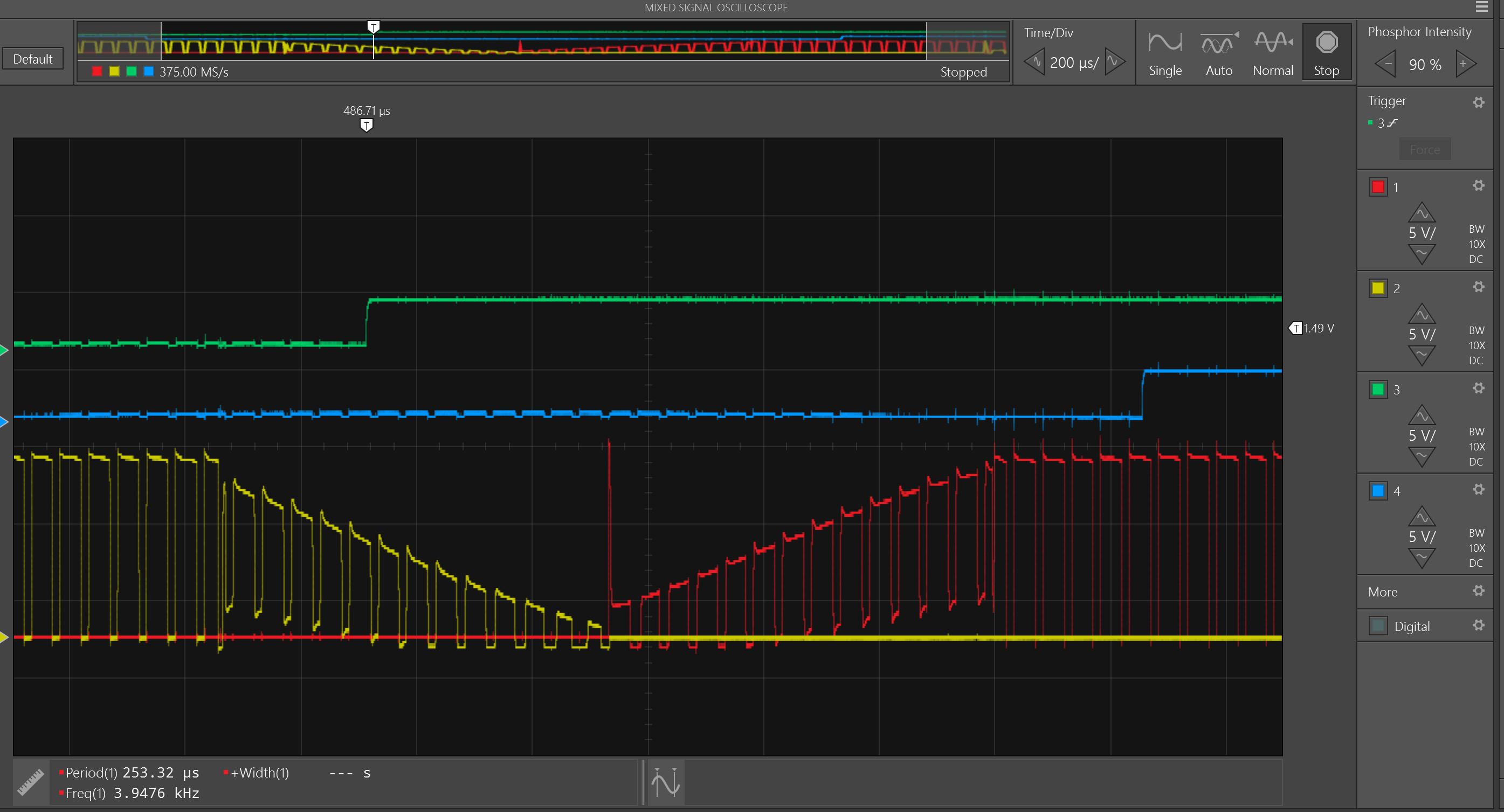
I made a BLDC control board to control an RC airplane motor- and it works well enough below 4k RPM, but goes unstable at higher RPM and loses sync. The type of control is sensorless trapezoidal high side PWM. This is the one where you use the ADC to sense the floating phase during the PWM "ON" duty, and then linear interpolate between the samples to find the exact time the signal would have crossed the Vin / 2 mark. That time is used to predict the commutation time. Inspiration came heavily from Dave Wilsons blog, TI appnotes, and Microchip appnotes.

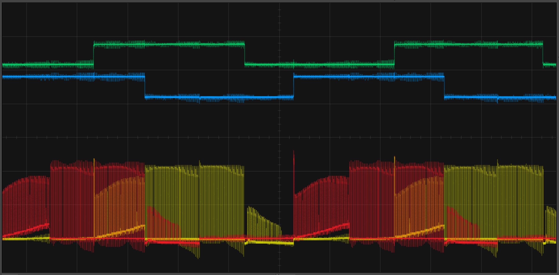
I am using a 4 sample binary filter where each bit is either < or > the Vin / 2 and the filter looks for 0011 or 1100. Then linear interpolation to find the exact zero crossing time between sample 2 and 3. If I run the motor open loop at a fixed pwm and commutation cycle combo, I can adjust the power supply voltage until the motor is running ultra smooth and whisper quiet. So the instability is coming from my control algorithm somehow.

Per the theory the zero crossing occurs 30 degrees into a 60 degree commutation step, so if I identified the time of the zero cross TZCD, the proper commutation step time under steady state conditions would be 2 * TZCD. But that doesn't work. What works is to take the difference between the current commutation period and 2 * TZCD and add a fraction of it to the current commutation time:

Tnew = Tcurrent + B * (2 * TZCD - Tcurrent), where B is some fraction, like 1/8 or something. If B is over .5 it doesn't work, and if B is less than .1 it doesn't work. But all the values of B which let the motor run also has it oscillating and the motor loses sync at over 4000rpm.

Has anyone made a sensorless BLDC motor controller and had a similar problem? Is there a better commutation or filter algorithm? I tried keeping track of previous Tcommutation with a running average but that doesn't seem to work unless the running average is less than 4 samples, and even then the oscillation is the same.

  • Hi Nick,

    A common problem with real time algorithms is interference from interrupts. Have you ruled this out?

    Another is latency. As the motor speed increases, the time between commutations is reduced. Attempting to commutate using the same algorithm at higher speed can lead to late commutations.
  • 100% sure its not the interrupts. The problem is with the way I use the zero cross time to predict when to commutate.

    1. Reset timer T on commutation
    2. Look for zero cross time Tcross
    3. Predict next commutation time and set the compare value for T: Tcommutate = Tcurrent + B* (2 * Tcross - Tcurrent)

    Tcurrent is the previous/current Timer T compare value, Tcommutate is the new Timer T compare value, Tcross is the measured zero cross time in counts. B is a scale factor, .25 seems to work.

    I'm sure there is a better way to predict the correct commutation time but I have no idea what that is. The app notes are really good about finding the zero cross and explaining the commutation cycle, but they are not so good on the exact algorithm. Most of them just say Tcommutate = 2*Tcross.

    This is the motor running. The green and blue are the hall signals. Go figure the hall signals are not aligned with where the motor needs to commutate, guess that explains why it won't run in sensored mode. Guess that's a cheap motor for ya. But every motor should run sensorless :( I would appreciate any hints about how to predict the correct commutation time.

  • Hi,

    I think you should capture this image when motor is coasting to find the hall sensor errors or you can capture by sniping motor freely with hand (without commutation).
    To find the commutation point, in zero crossing event, start a timer with period value equals to half the time between two zero crossing (half the time between previous and current zero crossing event). In timer period match ISR do the commutation. Adjust offset if any due to software latency etc.
    At higher speed make sure zero crossing detection is proper to avoid the speed oscillation. Because at higher speed number of PWM in one commutation will be less and during PWM off time you will not get zero crossing, it will lead to position (commutation) error. If number of PWM cycles is very few (< 2 or 3) in one commutation, increase the PWM switching frequency.

    Thanks
    Abhishek
  • Thank you for responding Prashant- I am pretty new to motors. I will work harder on my filtering and linear interpolation. It seems plausible that small inconsistencies could cause big problems at higher speeds.

    Let me clarify my ignorance about the difference between sensored and sensorless mode. So here is the same motor running approximately the same speed in sensored and sensorless mode. From the sensorless mode capture, it looks like the sensors are triggering on the BEMF zero (or power supply 50%) crossing. In sensored mode, the current is switching when the sensor switches!

    I think that means in sensored mode the coils are switching 30 degrees late, during which time it is slowing down the motor. Sensorless operation is qualitatively quieter and uses a little less current, indicating it is more efficient. Is it common to create a 'phase-shift' for sensored motors to try and get them to switch closer to the right time?

    Sensorless:

    Sensored: