This thread has been locked.

If you have a related question, please click the "Ask a related question" button in the top right corner. The newly created question will be automatically linked to this question.

DRV8303: DRV8303 GVDD drops down to 2.3V

Part Number: DRV8303
Other Parts Discussed in Thread: CSD19534KCS,

Hello

I have some hardware designed around the DRV8303 and I have the motors running smoothly, however as I increase PVDD (to less than 55V with a small Nema17 sized motor running no load even) the GVDD voltages not only drops down to 2.3V and stays there. It then gives me a fault and it also seems to be damaged permanently as even after trying to reset and leaving the power off the 11V does not come back.

I am using CSD19534KCS fets with the bottom set all connected to a common LSS for current measurement through a single shunt.

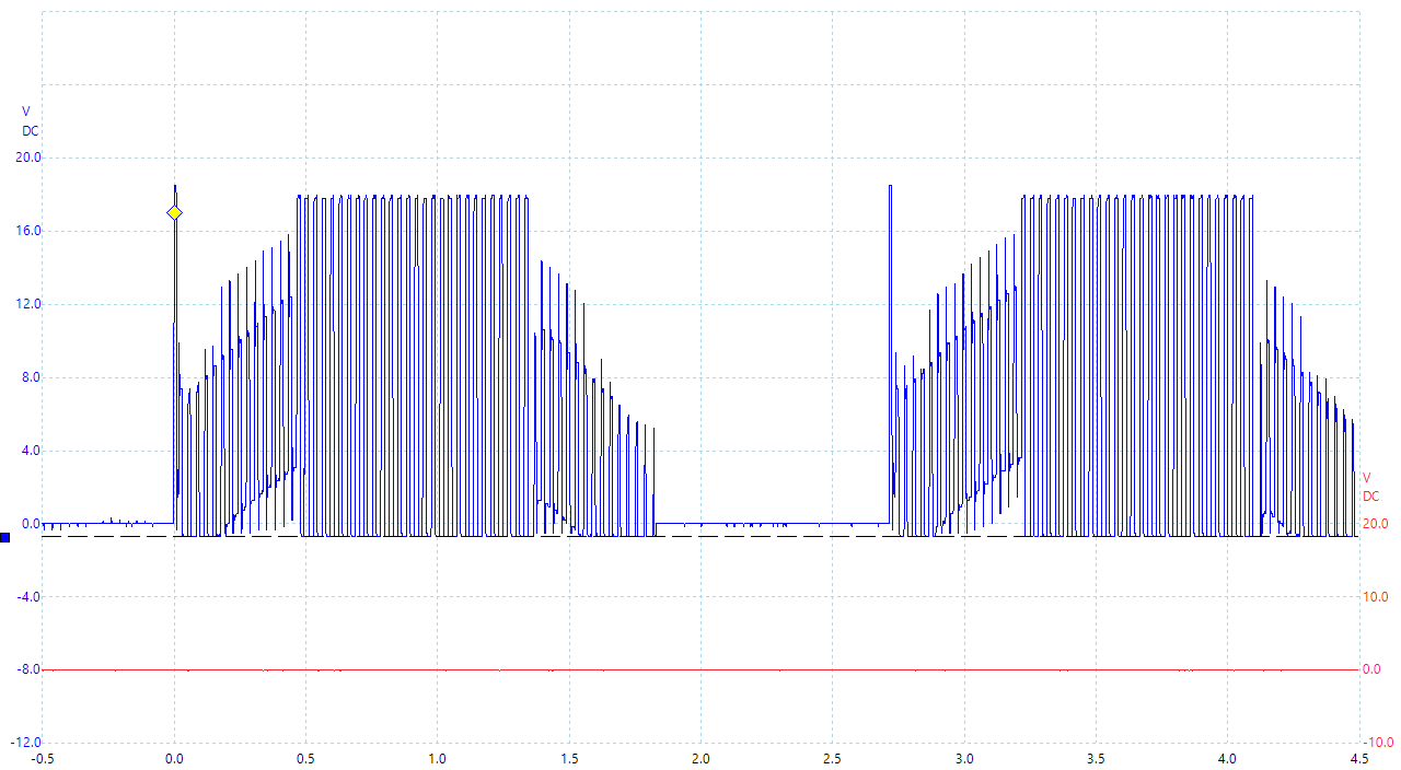
Below I have attached a Phase Waveform,

The first I noticed was the BEMF does look a little noisy but I put this down to the unshielded motor wires.

The second thing I noticed was the right hand slope being slightly lower than the left, this may be a slightly timing ussie so I will take a look at this in the programming.

Finally I noticed that the bottom of the phase drops down below GND.This is Odd and I am not sure how this has happened. There are no GND loops (that I can tell) an I am nnot sure if perhaps this is the cause for the GVDD failure?

I have also noticed that the charge pump fails as well as CP2 drop from around 10V to the same low 2.3V ish.

This has happened to a couple of PCB's now so it cant be a one off failure.

Thanks for you help

  • Hi Grady,

    What is the VM voltage in the image provided?
    How high was VM when the GVDD voltage dropped?
    Can you provide a schematic of the DRV8303 and the components around it?
  • Morning Rick

    On the Image I have only used around 17.5V, I was completing more tests at lower voltages as i did not want to risk damaging more boards.

    I am not sure exactly, but it must have been below 52V as this is the project specification and I did not reach the target. Again I do not really want to repeat the test and damage another PCB.

    Below I have tried to capture all the important components to the motor drive, the smaller 5V caps are bypass and are mounted near their partner IC's.

    Let me know if you need more information, I want to try get this issue resolved today if possible.

    Thanks

  • Hi Grady,

    Thank you for the images. There are a couple of items to address:

    1) Can you please check if the thermal pad is connected to GND? This is required for proper device operation per the datasheet.

    2) How are you connecting LGND and PGND? If the voltage on LGND and PGND separate by too much, the low side FETs can inadvertently turn on, or the absolute ratings could be violated.

    The DRV8303 GND and the PGND should be the same ground to prevent these conditions.
  • Hello Rick

    Yes, the DRV8303 is connected to a fairly large GND plane through 6x 0.6mm bore via's with no thermal relief.
    The LGND and GND are connected to each other via a 0 OHM resistor RC0603JR-070RL. I have measured the GND potential and it is very small.

    Graham
  • Hello Again Rick

    Just trying to get more information through to you, I was reading through the datasheet and noted the Vsl_max which I think is the source of the low side mosfets (in my case they are all joined together). Below is a scope capture of what I found.

    As you can see we have voltages around +/- 2V ( at around 31Khz (my PWM frequency) and aslo seems to go in a nice sine wave as well). The datasheet however states that the max voltage rating for Vsl_max is only +/-0.6V. Could this be a potential reason for the failure of Vgvdd and if yes, hand how can I get around it? You may notice I already have a 0.1uF cap between the low side source's and PGND, do you think maybe that I need a TVS or a pair of clipping doides?

    Thanks

  • Hi Graham,

    Violating the absolute maximum ratings could damage the device. If you are seeing these large swings at 17V, it will probably get worse as the voltage increases.

    Prior to adding additional circuitry, please look around the board and try to determine the reason for this.

    One item I noticed is the RC time constant of the SO1 filter seems to be very long. This could lead to delays reading the current.

    What is the dead time used for the device? What gate_current setting are you using?
  • Hello Rick

    I have gone over the hardware many times, All the power traces/shapes are large and I have used a 2Oz copper thickness. There is no chance of any loops that I can see. I have lowered the gate current down to 0.25A to see if this stops the sharp edges of the PWM. I am having a few problems with the SPI but they seem to be reading and writing OK now, just need to test the gate current still. If that fails I am going to look at increasing the size of the gate resistors.

    Yeah, I need a large time constant as I am using a low cost IC and only need very basic current measurement. I don't need accurate nor fast current measurements as the load fluctuates too much, I just wanted to smooth it all out.

    I am using the standard 10 Ohm resistor, I could have shorted to GND to get 50ns as the turn on/off time is only low, 50ns would have been OK but I thought I would give a little extra dead time just in case.

    Regards

  • UPDATE

    I have got the SPI working both writing to the registers and reading them to ensure the data is actually saved correctly.

    I have set the gate current to 0.25A, and this seems to help a little, however the spikes come back with vengeance when I load the motor up only sligtly (by hand). The spikes are getting up to 5.5V high...

    I increased the time base on the scope and found something interesting, the large spikes are not related to every phase commutation, but only every 8, and perhaps by coincidence we have an 8 pole motor!... So the spikes occurring once per mechanical revolution? Perhaps slightly Odd... below is the graph so you can see.

    On this trace the spikes occur every 28.95ms making the motor speed around 2072RPM...

    One more thing, on the datasheet by the recommended operating conditions is states max output capacitance on current shunt is 20pF. I don't see how but could this affect the failure of the IC? I think the recommended design uses 2200pF.

    Thanks

  • Hello Rick

    I am getting a little desperate with this, I have lowered the gate current, increased the gate resistors, added diodes and caps on the low side source and power GND and I still cant get close to 48V without the GVDD dropping. I have replaced the DRV8303 on all the boards to continue testing but nothing seems to be working.

    There has to be something causing the failures. Below is the last waveform I got before I powered down and tried to accelerate up again before GVDD went. It looks OK to me

    Thanks

  • Hi Grady,

    A few more items to check:

    What is the voltage rating of the CP1/CP2 capacitor? It should be rated for >63V.
    If you are willing to send the layout, we can look at it for possible causes.
  • Hello Rick

    I have sent a PM with the PDF's of the layout etc.

    CP1/CP2 is rated to 100V and the GVDD still drops down.

    Below is a scope catch of the GHC and the GLC, I am only running this test on 12V to limit any further damages. As you can see the GLC looks good, but the GHC seems to have the Phase C wave imposed into it. Could this be causing the failure?

    Thanks

  • Hi Grady,

    This should not be causing the failure. In fact, it is expected.

    The gate of the high side FET is either connected to the BST_x pin to provide the VM + ~12V to turn on the high side FETS, or connected to SH_x pin to create 0V Vgs.

    This can be seen in the Functional Block Diagram ( Section 7.2 ) of the datasheet.

    During the times when both the low side and high side FETS are off, the gate of the high side FET will have the phase voltage imposed on it.

    What is not expected in the image is the phase voltage from the time the high side FET is disabled to the low side FET is enabled. The BEMF should have been higher than 8V and dropping, almost the reverse of the phase voltage from the time the low side FET is disabled to the high side FET is enabled.
  • Hello Rick

    Yeah, I thought this was a timing problem with the halls, but I think its just the motor I was using. When I tried it with the DRV8303EVM and increase the duty cycle the current ramps up (when the motors under no load). I assume its messing with the Bemf integral formula the instaspin BLDC uses.

    However, the lower voltage trailing BEMF occurs with any motor that I try using either the DRV8303EVM or my pcb when the voltage increases. Below is a waveform of the DRV8303EVM running 48V on a larger motor.

    What I have noticed is that the DVR8303 has lower value gate resistors, dead time resistor and also has additional smoothing caps? (C87 & C88). My thinking is surely larger gate resistors and dead time is preferable (if we are having issues) but do I need the additional caps? My waveforms look fairly clean so I would not have thought so, but what do you think?

    Finally, from probing the DVR8303EVM its is clear that the its driving using the 6 PWM mode (not the 3 PWM) however the top and bottom drives are still synchronized (giving fast decay, 4Q operation). As I am only using a small PIC16F on this project I cant program this into the MCU. Do you think that perhaps as the GVDD is supplying the low side gates for a longer time period (I PWM the top gates) that maybe the charge pump cap cant work properly and hence making GVDD eventually fail on higher voltage? How would you suggest resolving this if it is the case? (perhaps larger CAP on GVDD?)

    Thanks