This thread has been locked.

If you have a related question, please click the "Ask a related question" button in the top right corner. The newly created question will be automatically linked to this question.

BOOSTXL-DRV8301: Strange output of BOOSTx

Part Number: BOOSTXL-DRV8301
Other Parts Discussed in Thread: LAUNCHXL-F28027F, DRV8301

Hi everyone,

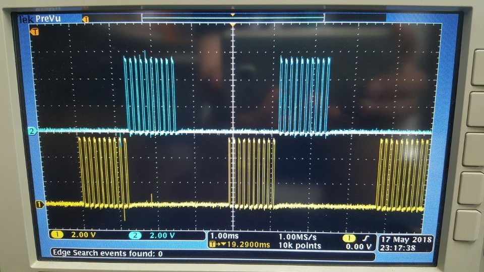
I'm trying to control a 12V sensorless BLDC (hard disk drive motor) using Arduino Uno and BOOSTXL-DRV8301 boards. Since the sensorless BLDC control requires 6-PWM mode, I made 6 soft PWM signals from the Arduino at around 7.8KHz, 30% duty cycle. To control the BLDC I implement 6 steps switching. Each step is switched each 0.6ms. (the below image shows 2 of 6 PWM channels (PWM-AH, PWM-BH) from the Arduino)

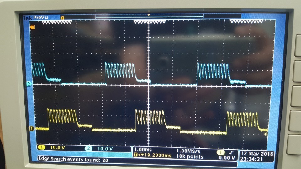
I connected these 6 PWM channels to the BOOSTXL-DRV8301 board without any level shifter since the datasheet only said that the minimum high logic for input pins is 2V. I used the default configuration setting for the BOOSTXL-DRV8301 so there was no SPI connection between 2 boards. Without any load at the output of the BOOSTXL-DRV8301 board, phase A and B are shown in the below image

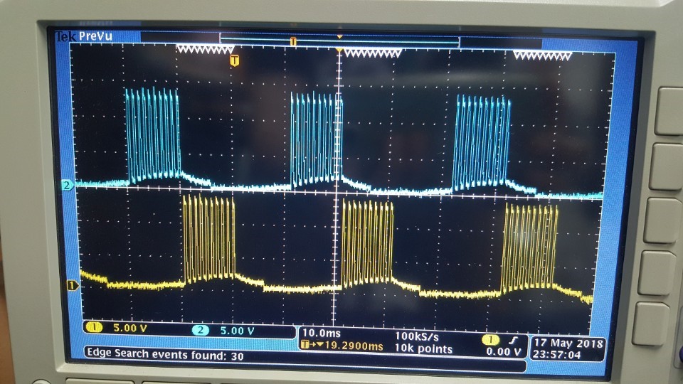
When I plugged the motor in, the motor didn't work and the phase voltage in phase A and B were like that:

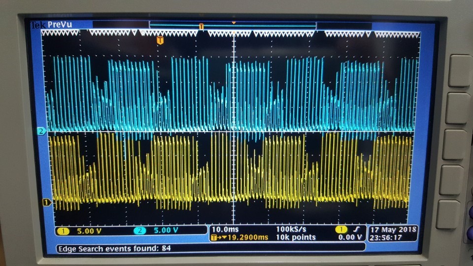
When I tried changing the PWM to 0.98kHz and step switching time to 5.1ms

the motor started to work but rotated at low speed and quickly became hot.

Could anyone explain the problem?

Thank you so much in advance.

  • Hi Khanh,

    Have you considered purchasing a LAUNCHXL-F28027F to complement the BOOSTXL-DRV8301? This will allow you to run the motor using existing code, and evaluate how the inputs and outputs should operate.
  • Dear Rick Ducan,

    Thank you for your quick reply.

    Before, I have considered using a LAUCHXL to utilize the existing code but it uses a ARM processor while my design uses AVR. (I wanna design my own simple ESC). And I thought it must be very easy to use the DRV8301 since I only need to control the speed of the BLDC as a blower (speed control without load). However, when I applied the commutation using 6 PWMs, the output of the BOOSTXL-DRV8301 is very strange as mentioned above. Do I need to configure the BOOSTXL-DRV8301? Now I'm using the default config.

    By the way, what is the relationship between the motor speed - PWM duty cycle - phase switching frequency? As my understanding, the motor speed is proportional to the PWM duty cycle. When the speed increases, the commutation time decreases as the consequence. Therefore, to control the speed of the BLDC, we only need to control the PWM duty cycle. Is that right?

    Best.

  • Hi Khanh,

    "Before, I have considered using a LAUCHXL to utilize the existing code but it uses a ARM processor while my design uses AVR. (I wanna design my own simple ESC). And I thought it must be very easy to use the DRV8301 since I only need to control the speed of the BLDC as a blower (speed control without load). However, when I applied the commutation using 6 PWMs, the output of the BOOSTXL-DRV8301 is very strange as mentioned above. Do I need to configure the BOOSTXL-DRV8301? Now I'm using the default config."

    Using the LAUNCHXL-F28027F is a good idea because the signals can be observed. The signals can be used to determine how to drive the motor.

    "By the way, what is the relationship between the motor speed - PWM duty cycle - phase switching frequency? As my understanding, the motor speed is proportional to the PWM duty cycle. When the speed increases, the commutation time decreases as the consequence. Therefore, to control the speed of the BLDC, we only need to control the PWM duty cycle. Is that right?"

    This is true to a point. There are protection features in the DRV8301 which will disable the outputs if the current increases above the VDS trip level. Since you say the outputs are not loaded during the scope captures, the protection features should not be activated.

    What are you doing with the GL_x signals at the beginning? The GL_x signals should be high to initially charge the bootstrap capacitors.
  • Hi Rick,

    The reason I used another MCU because I need to communicate with some other sensors and a Raspberry Pi. I have no idea that LAUNCHXL can obtain the data from the sensors and receive the commands from RaspBerry Pi while controlling the BLDC or not. I have briefly looked at the specifications of the LAUNCHXL, it seems that LAUNCHXL-F2802F can't do those. 

    For the GL_x signals, it was my mistake not to set them to high at the beginning. Let me try it.

    Thanks for your help.