This thread has been locked.

If you have a related question, please click the "Ask a related question" button in the top right corner. The newly created question will be automatically linked to this question.

DRV10970: Power current of the VM

Part Number: DRV10970

Hi team,

According to the diagram of the DRV10970, My customer want to know below information:

1. The MOSFET is connect to the VM, what's the cap value between the Drain and Source electrode?

2. Is there any requirement for the raising edge for the supply voltage in VM pin. if the raising time is less than 100ns for the 12V supply voltage, will this cause the impulse current in the VM pin. If so, what's the maximum level of impulse current? if there is a equation for this?

Please help to look at above two questions.

Lacey

Thanks a lot!

  • Hi team,

    Please help to look at this issue.

    Because customer are planning to make the PCB so it's urgent for them to get the answer!

    Lacey

    Thanks a lot!

  • Lacy,

    1. The drain to source capacitance is on the order of 500pf.

    2. We have not characterized fast rise time on VM so I can't provide you a good equation for this behavior. Is the customer planning to have a rise time of ~100nsec. That seems very fast.

    Thanks,
    Brian
  • Hi Brian,

    Thanks for your reply!

    My customer mentioned in their application, there may be a fast power supply, so they want to know the current and the impact.

    In addition, my customer has bought a DRV10970 EVM and want to use the EVM to drive ZC32 motor.

     But now, they find if they connect the two Hall inputs, the motor can spin. If they connect three Hall inputs, the motor can’t spin.

      Can you help to give your comment for the issue? 

    What may be the cause and what’s the next step to debug?


    Thanks a lot!

    Lacey


  • Lacey,


    I have not encountered the issue where connecting 3 hall inputs causes the motor to not spin. Would it be possible to provide the current waveform of phase U in the 2 situations (2 hall and 3 hall)?

    Thanks,
    Brian
  • Hi Brian

    Thanks so much for your reply!

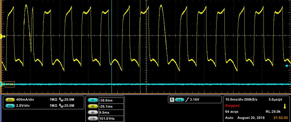
    Below is the signal tested in U phase pin

    1. it seems the signal is not the sin signal, Is the wave determined by the CMTMOD setting?

    2. Will the CMTMOD setting cause the issue I mentioned that when the EVM connect to the 3 hall inputs, the motor don't spin?

    3. Is there other setting in the EVM we need to consider?

    Thanks a lot!

    Lacey

  • Lacey,

    1. This is not a waveform that I've seen in the past. I expect to see either a sine or a trap waveform. CMTMOD and the hall placement do determine the behavior.

    2. CMTMOD setting should not cause the EVM not to spin, unless maybe if the hall placement doesn't match the CMTMOD selection.

    3. The only other settings are the DAA pin which controls the lead angle applied and the CS which sets the current limit.

    I think that we need hall signals, phase current and phase voltage wave forms at the beginning of the start up.

    Thanks,

    Brian

  • I believe that we have the motor up and running now. Still trying to help optimize the ability to run in both directions.