This thread has been locked.

If you have a related question, please click the "Ask a related question" button in the top right corner. The newly created question will be automatically linked to this question.

PMP4311: Output voltage drops on Load

Part Number: PMP4311

I am evaluating a PMP4311 design for 5KW PFC. The design difference is that I am using the boost inductance value to be half of what is mentioned in the BOM. Now the trouble is the output stabilises at 380Vrms on 'NO LOAD', but as soon as I apply a nominal load i.e. about 200Ohm approximately 2 A of load current; the output voltage drops to about 300V. I can see the switching pulse of gate driver on an Oscilloscope. The input is 230VAC at 50 Hz. Any suggestion as to what the issue might be ?

  • Hi Amardeep,

    An AE will help you soon but it may be delayed until tomorrow before you see an answer. I hope this is OK.
  • Another thing I noticed is that the current is peaky when I have the load connected. No PFC operation as well!

  • Hey Brian,

    Its been a week and haven't heard from any of you guys. Can you get me in touch with any of your AE ?
  • I sent this to the AE again, sorry for the late response Amardeep.
  • Hi, Amardeep

    Since the gate driver switching pulse , could you check the PFC inductance saturated current. Since you selected smaller PFC inductance, the peak current of PFC inductor could be high to saturate PFC inductor. Then the output voltage could be same as peak input voltage.

    BR
    Yunsheng
  • Hello Yunsheng,

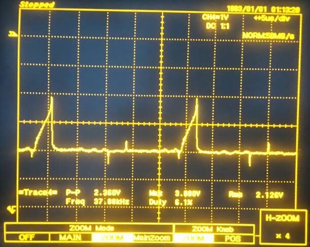
    I manage to get hold of old inductor of 340uH. But still the output seems to drop on load. Have attached the CT waveforms for your reference

  • Hello Yunsheng / Brian,

    Well I managed to get the PFC working but apparently unable to get it to operate at full load. Above 50% load the MOSFET drivers seem to fail. Anyone who can help me with UCC27322 would be great!
  • Let me see if an AE on the Driver Team can assist you Amardeep.
  • Amardeep,

    I am an applications engineer for the gate driver products. Could you please share more about the failure condition?

    1. What are the symptoms of the failure? Are any pins shorted or open? 

    2. An oscilloscope capture of the gate driver IN and OUT pin waveforms during functional and failure conditions would be useful.

    3. If the load is reduced, does the gate driver start working again?

    4. Is the circuit implemented on a PCB? If so, is it the same layout as the PMP4311 reference design, or did you make modifications?

    Please let me know the above items so we can start working together toward debugging the behavior you have observed.

    Regards,

    - Daniel

  • Hello Daniel,

    Appreciate the prompt response.

    1. What are the symptoms of the failure? Are any pins shorted or open?


    Well I killed the driver quite few times. Most of the times when the driver failed the VDD, AGND and PGND pins were shorted. During those times it was easier to identify.

    Last week I killed two driver which showed a different sort of failures, the pins weren't shorted but as soon as I powered the board the Driver started to smoke.

    2. An oscilloscope capture of the gate driver IN and OUT pin waveforms during functional and failure conditions would be useful.


    Well I can get you the Input waveform but little reluctant to probe the Out waveform as I am using the PMP4311 design which is non isolated and don't want to blow up my Mosfet's.

    3. If the load is reduced, does the gate driver start working again?


    No. Once failed it has to be replaced. It sinks in too much of current and smokes up.

    4. Is the circuit implemented on a PCB? If so, is it the same layout as the PMP4311 reference design, or did you make modifications?


    I am using the same layout. Though I have made few modification like the CT termination is 15Ohms, Mosfets being used are STW69N65.

    Hope this data helps! Let me know if you need more details.

    Thanks,

    Amardeep

  • Hey Daniel,

    Any leads on the issue ?

    Regards,
    Amardeep
  • Hello Brian,

    I found one of the discussions on the forum realted to UCC28070 which is similar to the issue that I am facing.
    Following is the link to that discussion:
    e2e.ti.com/.../2220324

    Can you guys suggest what is the workaround for such QVFF hysteresis issue.

    P.S. Hope that someone from TI responds!

    Regards,
    Amardeep

  • Amardeep,

    I apologize for the delay. I have been on business travel and had a hard time keeping up with e2e. I have reviewed the info you provided and have not found anything specific with the gate driver.

    Did you see the latest reply from Winston Chang on a workaround on the thread you linked to?

    - Daniel

  • Daniel,

    I checked-out the workaround that Winston Chang provided and I am working to incorporate that changes on the test board that I have.

    I have a hypothesis on why the drivers were failing! Though I am not sure if that is valid.
    I believed that the current demand at peak loads was not met by my SMPS, So I powered up the board using an external source to deliver 13 volt dc with current limited at 1A. This time when the failure occurred I blew up one arm completely.
    So my assumption is that since the on-board SMPS isnt designed to deliver that amount of current, it was in a way protecting the FET's, since the excessive current demand would cause the o/p voltage to drop thereby turning off the PFC controller and the gate drivers. This however somehow used to fail the gate driver's.

    Regards,
    Amardeep