This thread has been locked.

If you have a related question, please click the "Ask a related question" button in the top right corner. The newly created question will be automatically linked to this question.

TIDA-00508: Data flow information about TIDA-00508

Part Number: TIDA-00508
Other Parts Discussed in Thread: LDC1314, MSP430F5528

Hi,

We would like to know detail about data flow information about TIDA-00508.

I understand that MSP430F5528 read register value of LDC1314 and MSP430F5528 send data to PC upon request.

However, I don't know what kind of data is communicated b/w LDC and MSP430, MSP430 and PC.

So if you have figure of data flow about TIDA-00508, could you please send it me ?


Best Regards,

Machida

  • Hi,

    Could you please send me your feedback ?

    Best Regards,

    Machida

  • Hi,

    Is there any information ?

    BR,

    Machida

  • Hello Ryuuichi,

    Sorry for the delay in response.

    We do not have a data flow diagram for this application.

    Basically, the data going from the LDC1314 is the raw measurement data of the sensor frequency shift (which is a function of the sensor inductance). The processing of the data is detailed in the application note.

    What do you need to do?

    Regards,

    Chris O

  • Hi Chris-san,

    Thank you for your reply.
    >The processing of the data is detailed in the application note.
    Yes, I recognize what kind of processing is performed on PC.
    However, we can not understand what kind of data is used to perform processing of PC.

    >What do you need to do?
    Customer just want to know what kind of data is sent from EVM to PC to perform above processing of PC.
    I believe that conversion value of LDC1314 register is sent to MSP430, however we do not know what kind of data is sent from MSP430 to PC.
    Could you clarify data which is sent from MSP430 to PC to perform processing of PC ?

    BR,
    Machida
  • Hi Machida,

    The data is sent through the USB as a virtual COM port. The output data from the LDC1314 is sent in a binary format, and corresponds to the output conversion read from the 4 channels of the LDC1314. The conversion data is sent as 4channels x 16 bits of data for each conversion, and the data is streamed with new conversion results transmitted as the LDC1314 completes another conversion.

    Regards,

    ChrisO

  • Hi Chris-san,

    Thank you for your reply.
    Does MSP430 send only conversion data to PC ?
    How about calibration data ?

    BR,
    Machida
  • Hi Chris-san,

    Is there any update ?

    BR,

    Machida

  • Hi Chris-san,

    According to source code, it seems that calibration data and EVM default setting data are stored in following address of flash.

    --

    /** Defaults */
    #define INFOD_START (0x1800)
    #pragma DATA_SECTION(FlashConfigD, ".infoD")

    #define INFOC_START   (0x1880)
    #pragma DATA_SECTION(FlashConfigC, ".infoC")

    uint16_t  FlashConfigD[EVM_DEFAULTS_SIZE*sizeof(uint16_t)];

    uint16_t  FlashConfigC[CALIBRATION_LENGTH*sizeof(uint16_t)];

    --

    When I confirmed how user read above structure, I found following function.

    void set_flash_block(uint8_t num)
    {

      switch(num)
      {

      case 4: flashpointer = & FlashConfigC[0];

        break;

      case 5: flashpointer = & FlashConfigD[0];

        break;

      defaut: break;
      }
    }

     According to above, it seems that calibration data and EVM default setting data are read from above address.

    However, we do not know what default data is written in these region.

    Could you please provide detailed information about these region data  ?

    Best Regards,

    Machida

  • Hi Chris-san,

    Is there any update ?
    1. We want to confirm which data is communicated b/w PC and EVM.
    2. We want to know the detailed data which is commnicated b/w PC and EVM.

    I believe that answer of 1st question, calibration data and conversion data from LDC1314 are sent to PC. However, we do not know what data is communicated PC to EVM.

    I believe that answer of 2nd question, calibration data is stored in following region.

    #define INFOC_START (0x1880)
    #pragma DATA_SECTION(FlashConfigC, ".infoC")

    uint16_t FlashConfigC[CALIBRATION_LENGTH*sizeof(uint16_t)];

    However, we do not know the exact data which is stored above resion.

    At first, we do want to know about answer of below.

    >However, we do not know what data is communicated PC to EVM.
    >we do not know the exact data which is stored above resion.

    Best Regards,
    Machida
  • Hello Machida-san,

    My apologies on the delay. The protocol used in communication is not a binary format, rather it uses the ASCII protocol described below:

    Register Write:
    IW_<I2C address, 2 chars Hex>_<2char hex register>_<4 char hex write data><CR><LF>

    Register Read:
    IR_<I2C address, 2 chars Hex>_<2char hex register><CR>

    Dial responds with 4 characters corresponding to the Hex register contents.

    All alphabetic chars (A..Z) must be capitals, not lower-case.

    In the protocol above, "_" in the above is actually a space " "(ascii 0x20).

    As for the data, the cal data that is the linear correction data described in section 5.1.1 of  and the phase skew correction described in section 5.1.4. This data is transmitted as a virtual register address to the GUI. You can also look at section 6.1.

    Regards,

    ChrisO

  • Hi Chris-san,

    Thank you for your reply.

    - 1 -

    I understood how to encode the communicated data.

    Now, I am tring to capture USB data by using analyzer, and I recognized following commands are used.

    "VV", "IR", "FB", "RB" and "*".

    I understood that meaning of "*" and "IR" command from user's guide of TIDA00508

    *: This command requests the firmware to send the sensor output data, each 16-bit long, in the following sequence: Ch0, Ch1, Ch2, Ch3

    IR addr reg: Requests the firmware to send the 16-bit content of register reg of the I2C device having address addr

    However, I could not understand meaning of following commands.

    "VV", "FB" and "RB"

    Could you explain meaning of above commands ?

    - 2 -

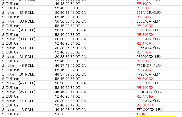
    Here is a part of captured data.

    I guess that TIDA00508 Diag demo board send data of flash in following communication.

    I guess that linear correction data and phase skew correction data which you described in previous thread are included.

    Could you please which region is for correction data and phase skew correction data ?

    Best Regards,

    Machida

  • Hi Chris-san,

    Sorry for posting several times,

    However, I have comment about Question "-1-" and "-2-" which I posted.

    For Q1 : I found meaning of command in "Notes.txt" which is stored in ../TIDA-00508 Inductive Dial-1.0\EVM Firmware\source.

    So, please ignore my first question.

    For Q2 : I need to change attached figure because conversion of ASC code was incorrect. So please confirm below.

    --

    - 2 -

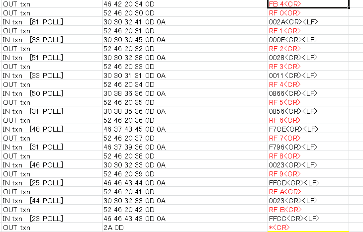
    Here is a part of captured data.

    I guess that TIDA00508 Diag demo board send data of flash in following communication.

    I guess that linear correction data and phase skew correction data which you described in previous thread are included.

    Could you please which region is for correction data and phase skew correction data ?


    Best Regards,

    Machida