This thread has been locked.

If you have a related question, please click the "Ask a related question" button in the top right corner. The newly created question will be automatically linked to this question.

TIDA-01606: "DNP" Transistors, gate isol. transformers

Part Number: TIDA-01606

Hello!
I have a question about TIDA-01606 when I start assembling a power board, I saw that in the assemble instructions, the main transistors of the half bridge (for example, Q1 and Q2) are marked with DNP, is this a mistake or something else? Without them, how much do I understand the circuit will not work?
Another question regarding the driver card transformers (T1, T2, T3), unfortunately, I did not find them on sale in WURTH Can you tell them, analogs, or send me to these transformers?
Thank you for your time!

  • Volodymyr,

    Thank you for identifying this mistake in our released file. The SiC MOSFETs were marked as DNP for our own internal production of the board, but are not meant to be for final production. These should be populated as expected. I will work to get the design files updated.

    Regarding the Wurth transformers, these were custom made for this project to achieve the desired output voltage in the open loop control system used. Likewise, the main power inductors in the output filter were also custom made by Wurth. You can reach out directly to a Wurth representative via their website to request these specific parts.

    Regards,

    Bart Basile

  • Thank you!
    But i don't know would Wurth provide me these specific parts in small quantity.
  • Hi Volodymyr

    I am working at Wurth and I support TI.

    We do provide samples and low quantities. Could you write an email to me with your contact information and your company/organization details?

    Thank you

    David Rosales

    david.rosales@we-online.com

  • Bart, 

    I think I found one more mistake in TIDA-01606 files.
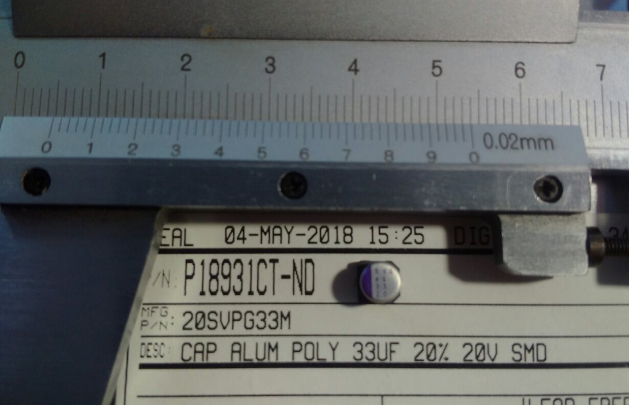
    About C48 and C126 - 20SVP33M. I've bought them and saw that footprint is bigger:

    I think it can be BOM mistake and assembly drawings?
    In assembly drawings I saw, that C123 is 0603 smaller that footprint on PCB.

    Thank you for you`re time!

    Regards,
    Volodymyr Holodiuk.

  • Volodymyr,

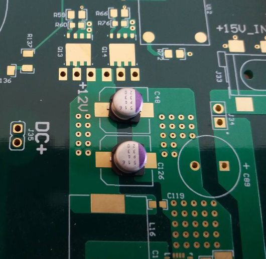
    There is either something incorrect with your fabricated PCB or the caps you have purchased for C48 and C126. This photo shows the correct ones installed:

    The Panasonic caps should also be about 5mm in diameter. Can you verify this with the ones you have?

    C123 is a 1205 sized cap, as also shown in the image.

    What source file did you use to have the PCB manufactured?

    Can you double check the total PCB size for me? It should be 350mm x 200mm.

  • Bart,

    Yes, it is 5mm capacitor

    And PCB size is 350x200

  • Thanks for the followup information Volodymyr. I believe I've located the discrepency.

    The design files that were published had the capicator updated in the schematic, but it wasn't pushed to the board files for some reason. Since the bom is created from the schematic, the part you have is as intended for the design, but the one on mine is actually 20SVP33M, which is an 8mm diameter.

    Both devices will work (with the 20SVPG33M having a lower ESR and slightly better performance). While not a perfect footprint match, it should still solder down for testing. Alternativly, if you can source the 20SVP33M, it will fit and work correctly as well.

    I apologize for the discrepency here, and do appreciate you letting us know so we can ensure our designs are correct.

    Regards,
    Bart