This thread has been locked.

If you have a related question, please click the "Ask a related question" button in the top right corner. The newly created question will be automatically linked to this question.

PROCESSOR-SDK-DRA7X: DCAN Interrupt is not triggered eventhough the CANRx line is fed with proper CAN data (verified via oscilloscope)

Part Number: PROCESSOR-SDK-DRA7X
Other Parts Discussed in Thread: SYSBIOS

Hello Team,

This Support is concerning an infotainment project relating to CAN communication with TI-J6 M4 Core. 

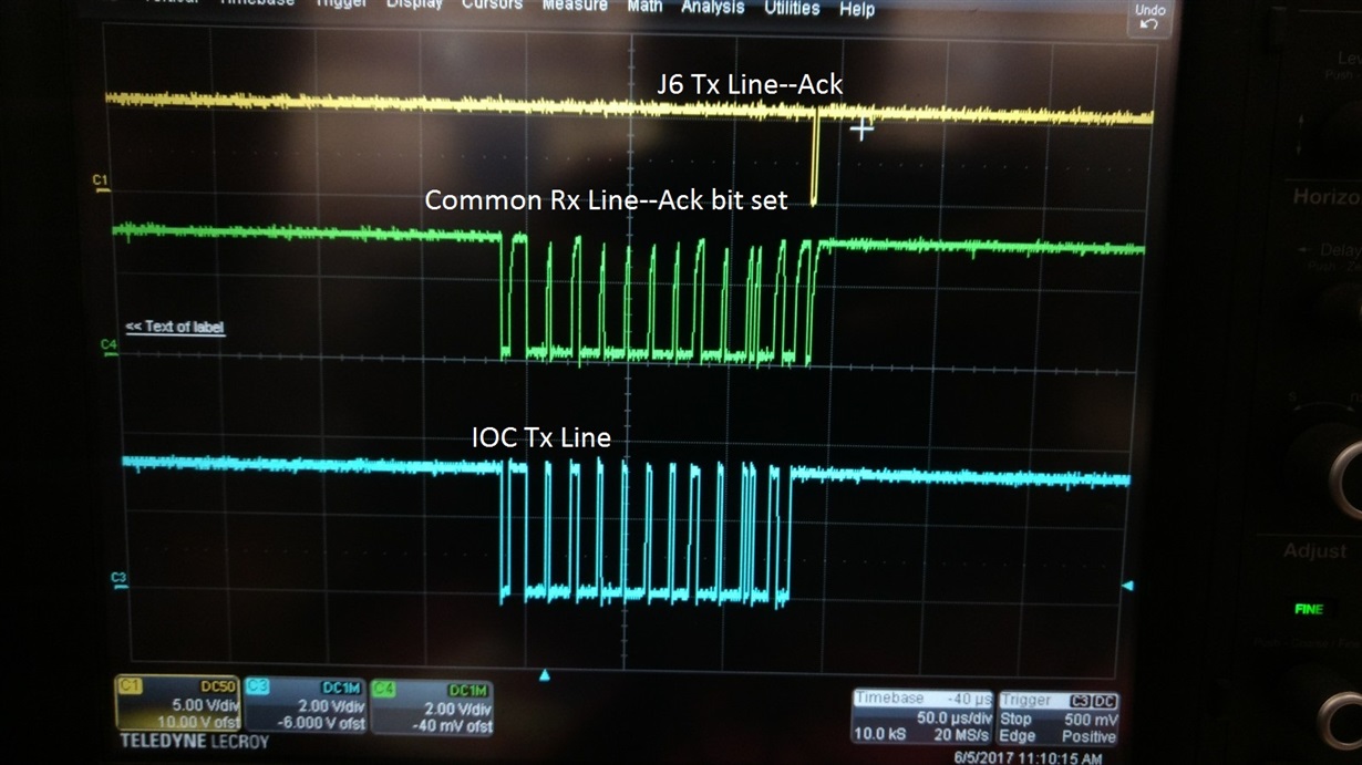
Currently in our project the CAN messages are being seen over the  CAN Rx lines of J6 M4 Core. But, the J6 M4 core is not able to receive these messages meaning no interrupt is being triggered by the CAN controller. 

We see that the J6-M4 core is  acknowledging  (Refer Image for more details where in the J6 Tx line is being acknowledged).the messages but unfortunately no interrupt is being triggered by the CAN CELL. 

Even though the message is acknowledged by J6 it is not passed on to the upper layers, could you please help us out here on what could be the issue.

Thanks!

Prashanth.

  • Hi Prashanth,

    First thing crossing my mind is whether you have set the correct routing of DCAN IRQs to the respective M4 core?
    Interrupt crossbar module is described in TRM section 18.4.6.4 IRQ_CROSSBAR Module Functional Description.

    Regards,
    Stan
  • Hello Stan,

    Thanks for the reply, I have verified the routing of the interrupt in the interrupt crossbar module reference and it looks fine.

    Can you suggest some other options.

    Thanks!

    Prashanth
  • You said 'interrupt'. I want to make sure you have taken into account both interrupts (DCAN has 2 main IRQs and one ECC IRQ).
    Also, did you double check the M4 interrupt controller was configured properly?
    At last, can you please make dump of DCAN registers and post them here? DCAN has many bits describing its state.

    Thanks,
    Stan
  • Hell Stan,

    Thanks for the reply , I have verifed the configuration in interrupt controller and we are using DCAN1 and interrupts are enabled.

    Please find the core dump of DCAN register attached along with the mail.

    Register  Name Access Address Value
    DCAN_CTL RW 0x4AE3C000 0x0200140A
    DCAN_ES R 0x4AE3C004 0x00000010
    DCAN_ERRC R 0x4AE3C008 0x00000000
    DCAN_BTR RW 0x4AE3C00C 0x00001643
    DCAN_INT R 0x4AE3C010 0x0000003F
    DCAN_TEST RW 0x4AE3C014 0x00000010
    DCAN_PERR R 0x4AE3C01C 0x00000204
    DCAN_ABOTR RW 0x4AE3C080 0x00000000
    DCAN_TXRQ_X R 0x4AE3C084 0x00000000
    DCAN_TXRQ12 R 0x4AE3C088 0x00000000
    DCAN_TXRQ34 R 0x4AE3C08C 0x00000000
    DCAN_TXRQ56 R 0x4AE3C090 0x00000000
    DCAN_TXRQ78 R 0x4AE3C094 0x00000000
    DCAN_NWDAT_X R 0x4AE3C098 0x00000080
    DCAN_NWDAT12 R 0x4AE3C09C 0x00000000
    DCAN_NWDAT34 R 0x4AE3C0A0 0xC0000000
    DCAN_NWDAT56 R 0x4AE3C0A4 0x00000000
    DCAN_NWDAT78 R 0x4AE3C0A8 0x00000000
    DCAN_INTPND_X R 0x4AE3C0AC 0x00000080
    DCAN_INTPND12 R 0x4AE3C0B0 0x00000000
    DCAN_INTPND34 R 0x4AE3C0B4 0xC0000000
    DCAN_INTPND56 R 0x4AE3C0B8 0x00000000
    DCAN_INTPND78 0x4AE3C0BC 0x00000000
    DCAN_MSGVAL_X 0x4AE3C0C0 0x000000FF
    DCAN_MSGVAL12 0x4AE3C0C4 0xFFFFFFFF
    DCAN_MSGVAL34 0x4AE3C0C8 0xFFFFFFFF
    DCAN_MSGVAL56 0x4AE3C0CC 0x00000000
    DCAN_MSGVAL78 0x4AE3C0D0 0x00000000
    DCAN_INTMUX12 RW 0x4AE3C0D8 0x00000000
    DCAN_INTMUX34 RW 0x4AE3C0DC 0x00000000
    DCAN_INTMUX56 RW 0x4AE3C0E0 0x00000000
    DCAN_INTMUX78 RW 0x4AE3C0E4 0x00000000
    DCAN_IF1CMD RW 0x4AE3C100 0x00F30040
    DCAN_IF1MSK RW 0x4AE3C104 0xfeff0800
    DCAN_IF1ARB RW 0x4AE3C108 0xda000000
    DCAN_IF1MCTL RW 0x4AE3C10C 0x00001480
    DCAN_IF1DATA RW 0x4AE3C110 0x00000000
    DCAN_IF1DATB RW 0x4AE3C114 0x00000000
    DCAN_IF2CMD RW 0x4AE3C120 0x00730040
    DCAN_IF2MSK RW 0x4AE3C124 0xfeff0800
    DCAN_IF2ARB RW 0x4AE3C128 0x00000000
    DCAN_IF2MCTL RW 0x4AE3C12C 0x00000080
    DCAN_IF2DATA RW 0x4AE3C130 0x00000000
    DCAN_IF2DATB RW 0x4AE3C134 0x00000000
    DCAN_IF3OBS RW 0x4AE3C140 0x00000000
    DCAN_IF3MSK RW 0x4AE3C144 0xFFFFFFFF
    DCAN_IF3ARB 0x4AE3C148 0x00000000
    DCAN_IF3MCTL 0x4AE3C14C 0x00000000
    DCAN_IF3DATA 0x4AE3C150 0x00000000
    DCAN_IF3DATB 0x4AE3C154 0x00000000
    DCAN_IF3UPD12 RW 0x4AE3C160 0x00000000
    DCAN_IF3UPD34 RW 0x4AE3C164 0x00000000
    DCAN_IF3UPD56 RW 0x4AE3C168 0x00000000
    DCAN_IF3UPD78 RW 0x4AE3C16C 0x00000000
    DCAN_TIOC RW 0x4AE3C1E0 0x0004000f
    DCAN_RIOC RW 0x4AE3C1E4 0x00040009

    Please do share your thoughts.

    Thanks!

    Prashanth

  • Prashanth,

    Unfortunately I can see only what you already know - DCAN looks configured fine and receives messages but they don't get read by the host.
    I don't know. Did it work ok with A15 core?

    Regards,
    Stan
  • Hello Stan,

    I have not tried the option of A15 core, I'm afraid checking if it works on A15 core might be an tough option, since it might lead to a lot of changes on the software side.

    In addition to the above registers I tried modifying the below registers with these two values.

    Could you suggest if this is fine.

    Register : CTRL_CORE_PAD_DCAN1_RX (0x4A00 37D4)

    Value 1: 0x01060000
    Value 2: 0x00060000

    Both seem to be not working.

    Is there anything else which i can check, such as checking what is the message ID of the CAN message received in the buffer or something? Or Trying the polling mode where we check periodically if the message is received or something.

    Thanks in advance!

    Best Regards,

    Prashanth.
  • Hi Prashanth,

    I was just asking if you already did check with A15 driver. I didn't mean to migrate to A15 core. Anyways.

    Pad configuration registers should be already ok, having in mind you can receive messages from CAN bus.

    I've dug inside the spec and found out that additional level of interrupt-enables does exist.

    CAN messages reside in RAM in so called 'message objects'. CAN bus being multicast, every node will receive every message on the bus, but application can decide which messages (by their 'message identifiers') are relevant. all others will be ignored.

    You already may know all this, sorry if so.

    My understanding  is that at least one message object should be configured for:

    - acceptance filtering,

    - Rx/Tx INTERRUPT ENABLE !

    -  message object enable.

    If not, no message object will generate an interrupt.

    I think you can quickly debug this by enabling the SIE interrupt (it is disabled now). This will cause every wakeup, transmit, receive, or error to fire an interrupt.

    Later, you will have to setup message objects and disable SIE again.

    Let me know if something happens with SIE enabled.

    Regards,

    Stan

  • Hello Stan,

    Thanks for your reply .

    I tried setting the SIE bit in the DCAN_CTL register to 1.

    Currently I'm seeing a value of 0x8000 in the DCAN_INT register, which according to the DRA7xx manual is DCAN_ES value is not 0x07.

    Also in the manual i find the below text

    "The value 0x8000 in the INT0ID field indicates that an interrupt is pending because the CAN core has

    updated (not necessarily changed) the Error and Status register (DCAN_ES). This interrupt has the
    highest priority."

    The DCAN_ES value what I see is 0x10 which means a message is received successfully.

    Does this value 0x8000 mean that interrupt is not triggered for some reason?

    Please advice.

    Thanks! 

    Prashanth.

  • Hi Prashanth,

    No, 0x8000 should simply mean that not a message object triggered an interrupt but DCAN_ES register has changed. Interrupt must be triggered now, because you had enabled it in SIE.
    Interrupt handler must be aware of 0x8000, poll DCAN_ES for bit change, and perform needed actions.
    That is, currently DCAN should be generating interrupts on every Rx (and other events). But SW driver may not be aware of 0x8000 (ES) interrupts.
    You can either modify driver to show to you 0x8000 interrupt triggers, or setup message objects as required (the normal workflow).

    Regards,
    Stan
  • Hello Prashanth,


    can you tell how the NVIC (M4/IPU) is configured for your test?

    Thanks, Stefan

  • Hi Prashanth,

    Looking at the register dump that you have provided, these register values are after receiving message, correct? Which DCAN interrupt (DCAN_IRQ_INT0/DCAN_IRQ_INT1) are you using? You should configure IRQ Crossbar accordingly. As Stan said before you have to enable/set DCAN_CTL.SIE bit. Also looking at 'DCAN_INTPND_X' and 'DCAN_INTPND34' register contents, interrupts are pending for mailbox number 63 and 64. Also corresponding bits are set in 'DCAN_NWDAT34' register, which means Message Handler or the Software has written new data into the data portion of these message object. Is this loopback application(because DCAN_TEST.LBACK bit is set)? If so, you are using one of mailboxes (from 63/64) as Tx mailbox and other one as Rx mailbox. Please confirm this.

    Can you provide your mailbox configuration(especially for mailbox number 63 and 64)?

    BR,

    Vivek Dhande.

  • Hello Stefan,

    We are using DCAN INT0 and the corresponding IRQ crossbar IRQ_CROSSBAR_222 is configured in CTRL_CORE_IPU1_IRQ_59_60 register( Physical Address :0x4A002828U) with value 0x00DF00DE.

    Do you need some more details, please do let me know?

    Thanks!

    Prashanth.
  • Prashanth,

    Please check the query from Vivek below. It is very important!

    "Can you provide your mailbox configuration(especially for mailbox number 63 and 64)?" mailbox = message object in TRM

    Vivek,

    I've noticed the Loopback bit was set, but some other bit configuration caused Loopback to be ignored. So they are not in loopback.

    I think they are using another J6 board for the bench (it is stated somewhere in the initial posts).

    Regards,

    Stan

  • Hello Vivek,

    Thanks for your reply.

    The Dump values are after receiving the message.

    We are using DCAN_IRQ_INTO and the correspoing IRQ crossbar 222 is configured accordingly in CTRL_CORE_IPU1_IRQ_59_60 register( Physical Address :0x4A002828U) with value 0x00DF00DE.

    The testing is not in loop back mode since DCAN_CTL is with value 0x0200140A, which means DCAN_CTL.TEST bit is zero which is normal operation and I understand this would disable .

    Regarding configuration mailbox of 63 and 64 do you expect me to provide me the below configuration details from the controller dump?

    Message RAM base address ( 0x4AE3 D000) + (message object number (in my case 63 and 64)) × 0x20

    Please let me know if this is what is expected

    Thanks in advance!

    Best Regards,

    Prashanth.
  • Hello Vivek,

    With the DCAN_CTL.SIE bit set to 1, the DCAN_INT is set to value 0x8000 and now DCAN_INTPND_X and DCAN_INTPND34 both are zero.

    Please find the attached register dump for more details.

    Thanks!

    Best Regards,

    Prashanth.DcanDump.xlsx

  • Prashanth,
    Yes, that is expected as a whole. Please note that last message object 64 is at offset 0x0, otherwise the formula is correct.
    Also note there are two methods accessing RAM.
    - One is using a debugger (TRM Debug/Suspend Mode)
    - Second is entering test mode and reading RAM with omapconf or devmem2 (TRM RDA Mode). This mode can be entered by DCAN_TEST[9] RDA bit is set while the DCAN module is in test mode (DCAN_CTL[7] TEST = 1)

    Regards,
    Stan
  • Prashanth,
    Can you please try one more thing. Please disable SIE, but disable also IE0.
    Run the test and read back the DCAN_IF1CMD RW 0x4AE3C100
  • Hello Stan,

    I have now disabled SIE and also IE0 current DCAN_CTL value is 0x02001408 and DCAN_IF1CMD is set to 0x00f30040

    Thanks!

    Prashanth.
  • HI Folks,
    I'm not sure if you have already checked this.

    I don't have access to the driver code but I would expect there should be an adaptation file in the driver where you register the ISR with the right interrupt number.

    Hwi_Handle Hwi_create(Int intNum, Hwi_FuncPtr hwiFxn, const Hwi_Params *params, Error_Block *eb);
    // Allocate and initialize a new instance object and return its handle

    Can you check if the HWI was registered with proper interrupt number as set in crossbar and ISR?

    Regards,
    RK
  • Prashanth,
    Did you reset the board beforehand? I.e.
    1. Reset
    2. Disable interrupts after boot
    3. Feed some CAN packets
    4. Dump IF1CMD register

    BR
    Stan
  • Hello Stan,

    I had modified the driver to disable the interrupts and SIE bit in DCAN_CTL register and flashed the code to MIB3 radio after which did an HARD reset.

    Then fed the CAN Messages to the radio and read the value of IF1CMD register, I guess this is same as what ever steps you had suggested.

    Thanks!

    Prashanth.
  • Hello RK,

    We invoke the Interrupt_Configure api (interrupts_sysbios.c file) with interrupt number as 59 and the corresponding mapping to IRQ_Crossbar relevant for DCAN is done. IRQ_CROSSBAR_222 is configured in CTRL_CORE_IPU1_IRQ_59_60 register( Physical Address :0x4A002828U) with value 0x00DF00DE.

    From the interrupt_configure api, the API you mentioned Hwi_create is invoked with interrupt number and the config handler for the intterupt as below.
    Hwi_create(id,config->handler, &params, &eb);

    Thanks!

    Prashanth.
  • Hi Prashanth,

    Sure. The reason I've asked you to do that is because I thought DCAN driver actually did receive interrupts.

    I thought so because I thought software had read message object 64 through IF1. This number is left in the DCAN_IF1CMD [MESSAGE_NUMBER] register while its reset value is 1.

    However, you have tested with interrupts disabled, and read same number (64). Thus now I'm absolutely unaware who had accessed message object 64 and even if this value means software has accessed it at all.

    I'm sorry, I don't have other ideas except to check if Erratum i893 DCAN Initialization Sequence was implemented.

    Regards,

    Stan

  • Hi Prashanth,

    Here you are only sending message to DCAN not receiving. Right?
    What message are you sending to DCAN? Which is appearing on the bus in provided snapshot. I mean message details like ID, controls bit and data.
    Also please provide the mailbox configurations especially for Rx mailboxes for acceptance filtering.

    BR,
    Vivek Dhande
  • Hi Prashanth,
    Any update on this? Please provide the information requeste dby Vivek incase thsi issue is still open and is being worked on.

    Regards,
    RK
  • Hello Team,

    Sorry for the delay in response I was off for sometime.

    The issue was with one of the register address used in configuration was incorrect and now the interrupts are generated but the only issue issue is I'm able to receive messages only for few seconds  (approximately around 4 secs), after which there is no reception of the messages and no interrupt is generated after this time.

    what could be the issue here? 

    Thanks a lot!

    Best Regards,

    Prashanth.

  • Hi Prashanth,

    Can you provide details on what register was configured with wrong address? This will benefit others who might face similar issue?

    On the message reception, it could be an interrupt miss, below suggestions are based on general SW race in interrupt handling. 

    Check how you are handling the interrupt in ISR, do you immediately mask/disable interrupt?

    Check for status of any pending requests. When does the SW enable the interrupt again / clear pending one?

    We have seen such a miss in other drivers where the ISR reads the status register and serves all pending requests but if an interrupt occurs just when the control is returned from ISR there's a chance of misisng interrupt and no new events will be generated until the pending one is cleared.

    Regards,
    RK