This thread has been locked.

If you have a related question, please click the "Ask a related question" button in the top right corner. The newly created question will be automatically linked to this question.

RTOS/TDA3XEVM: How to debug ethernet MDIO interface?I can not access the phy register.

Part Number: TDA3XEVM

Tool/software: TI-RTOS

Hello!

When I am debugging the MDIO interface,I encountered a strange question. I can not  access the phy  register.

Software and hardware environment is as follows:

bios_6_46_04_53
ndk_2_24_02_31
nsp_gmacsw_4_15_00_00

TDA2XX

Some of my analysis is as follows:

1、Use linux + bios system in tda2x, pinmux and Network driver configured in linux,mido function is OK,so I can confirm the hardware is OK.

2、but only use bioss ystem, I can not  access the phy  register.MDIO pinmux MCLK pin is0x30003(output)  ,MDIO is 0x70003(input)

3、some MDIO Register as follows:

myMDIO_VER:0x40070106

myMDIO_ALIVE:0x0

myMDIO_CONTROL:0x41000198

 myMDIO_LINK:0x0

Why the MDIO_ALIVE register is always 0?

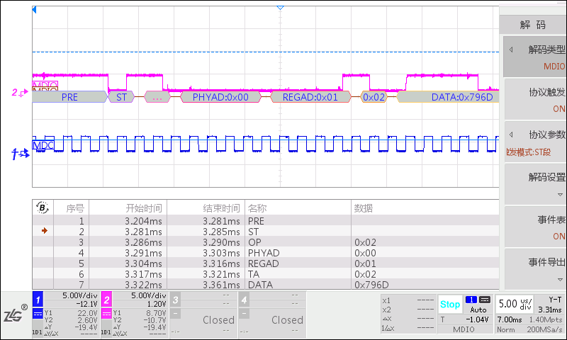
4、After the SOC is powered on,I use oscilloscope to measure the waveform of two pins of mdio:

Phy address 0 is responsive,but MDIO_ALIVE register is always 0,How can I debug it?

Thanks!

  • Hi,

    I have forwarded your question to NDK expert.

    Regards,
    Yordan
  • Hi,

    Are you working with the on-board PHY or external PHY? What is the make/model of your PHY if the latter case?
  • I use external PHY,and my mode of phy is KSZ9031.I think the hardware is ok,because using another software on my board is OK.

  • Please take a look at the following post. I hope it can be of some help.
    e2e.ti.com/.../600196
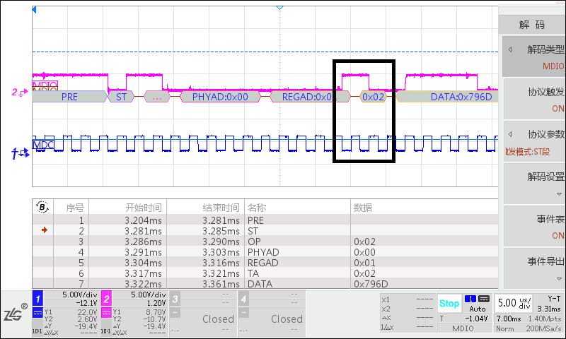
  • Thank you very much for your support, but that link does not solve my problem。Because from the following waveform view,TA bit is 0x02,and is OK.

    Maybe my English level is not very good, leading to unclear description of the problem, or what I was wrong with.Maybe I did not describe my use of the environment, and some of my test environment.The type of phy I use is KSZ9031,On the same board(SOC is tda2xx,phy isKSZ9031),Run linux system, the network is OK.However, run the BIOS system, MDIO can not access.So I think the problem lies in the vision_sdk nsp network firmware initialization,Such as the clock initialization, register configuration and so on.

    Thank you!

  • static void LOCAL_MDIO_FindingState(const MDIO_State *pMdio, PHY_Device *pPhy)
    {
        uint32_t *phyState = &pPhy->phyState;
        uint32_t phyMask = pPhy->phyMask;
        uint32_t phyNum, i, j, phyAcks;

        phyNum = PHY_NOT_FOUND;

        if ((*phyState & PHY_TIM_MASK) != 0)
        {
            *phyState = (*phyState & ~PHY_TIM_MASK) | ((*phyState & PHY_TIM_MASK) - ((uint32_t)1U << PHY_TIM_OFFSET));
        }
        else
        {
            phyAcks = myMDIO_ALIVE;MDIO_ALIVE register always is 0
            phyAcks &= phyMask; /* Only interested in 'our' phys */

            j = 1U;
            for (i = 0; i < (uint32_t)32U; i++)
            {
                if ((j & phyAcks) != 0)
                {
                    break;
                }
                j = j << 1U;
    }

  • Hi,
    Can you please confirm your pinmux values?
    "MDIO pinmux MCLK pin is0x30003(output) ,MDIO is 0x70003(input)"
    My doubt is because both MDIO pins must be in muxmode=0, but your values show muxmode=3.

    CTRL_CORE_PAD_MDIO_D register is at 0x4A00 3558 for TDA3x
    CTRL_CORE_PAD_MDIO_MCLK register is at 0x4A00 3554 for TDA3x
  • My SOC model is TDA2X, MDIO configuration is as follows:

    vin2a_d10 - MCLK
    vin2a_d11 - MDIO

    so my pinmux maybe is ok.Is there any other reason that will cause this problem? Can provide a debugging method? I do not know how to start.

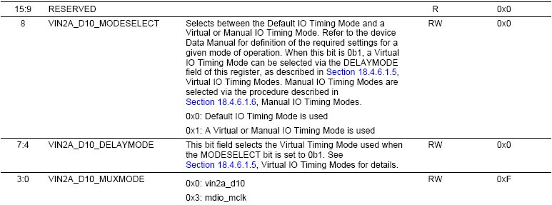
  • VIN2A pins need additional settings for timing. Can you check they are correctly set?

  • Just as a side note: You can always use the Pad Configuration Tool (PCT) to configure these pins, delay modes, etc. Dump the registers and see what the tool has configured for you. Then cross check with your SW configuration.

    Thanks,
    Alex
  • Hello,

    Can you please provide below details?

    1. Which PHY are you using?

    2. Is this TI EVM or custom board?

    3. Your software configuration? like PHY mode, pin mux setting and Board mux if any?

    As myMDIO_ALIVE is also zero i think issue is mostly due to wrong pinmux or boardmux missing. 

  • Hi Prasad,

    I will try to summarize feedback from user:

    "I use external PHY,and my mode of phy is KSZ9031. I think the hardware is ok, because using another software on my board is OK."

    "On the same board(SOC is tda2xx, phy is KSZ9031 I run linux system, the network is OK. However, run the BIOS system, MDIO can not access. So I think the problem lies in the vision_sdk nsp network firmware initialization, such as the clock initialization, register configuration and so on."

    "My SOC model is TDA2X, MDIO configuration is as follows:

    vin2a_d10 - MCLK
    vin2a_d11 - MDIO"

    "MDIO pinmux MCLK pin is 0x30003(output), MDIO is 0x70003(input)"

    "Phy address 0 is responsive (as seen from the screenshot), but MDIO_ALIVE register is always 0,How can I debug it?"

  • Hello Stan,

    Apart from enabling GMAC module and setting clocks the MDIO doesn't need any other configuration from NSP.

    In fact if you enable GMAC through gel files and enable MDIO module through CCS memory browser, you should be able to see PHY_ALIVE and Link_status getting set. So i strongly believe issue is due to, as said earlier, wrong pinmux or missing boardmux.

    Also drom the MDIO register values shared earlier, i see MDIO clock divider set to 0x198, why is it so? Normally we set it to 0x1F or 0x89.

    Is it possible for you to share schematics on my personal mail for review?

  • Thank you very much for your support!
    I want to confirm, the following two pins need to configure IODELAY parameters:
    vin2a_d10
    vin2a_d11

    From ti_components / drivers / pdk_01_07_00_16 / packages / ti / boot / sbl_auto / sbl_utils / src / tda2xx / sbl_utils_tda2xx_iodelay.c view is not configured, the software is OK on the EVM board, running on our board, I did not Change the IODELAY parameter

    But in actual operation, I read the following two registers have a value:
    CFG_VIN2A_D11_OEN RW 0x00000106
    CFG_VIN2A_D11_OUT RW 0x000000c8

    I do not know how these values are written in?

  • Unfortunately, I can not provide the hardware schematics, because the company has a confidentiality agreement, but I can be sure that my hardware is OK

    In addition to be able to provide the efficiency of information communication, can you tell me your email, to facilitate direct communication, quick solution to the problem, thank you
  • Hello,

    In TI EVM we are using default MDIO PADs for the MDIO pins (clock and data). It is configured in the default SBL configuration.
    As your board uses different MDIO pins you need to change the PAD mux to enable MDIO on vin2a_d10/11 pins.
    Also make sure you dont enable default MDIO pins otherwise there would be two PADs driving same signal.

    The sbl_utils_tda2xx_iodelay.c configures vin2a_d10 & vin2a_d11 for video functions which you need to change as well.

    Your aim should be to get PHY_ALIVE non-zero as it doesnt involve any NSP configuration. For functional issues we can debug NSP.