This thread has been locked.

If you have a related question, please click the "Ask a related question" button in the top right corner. The newly created question will be automatically linked to this question.

awr1243:Is the IRQ operation of AWR1243P different from IRQ of AWR1243?

Part Number: AWR1243

Recently I started using AWR1243P.

When AWR1243P starts MCSPI communication with TDA3xx, the IRQ is always HIGH and the initialization wait does not end.

Is AWR1243P different in MCSPI communication process from AWR1243?

Also , is the MCSPI of AWR 1243P communicating while IRQ is HIGH?

  • Hi,

    I will follow up with the team with respect to any differences between AWR1243 and AWR1243P.

    To understand the phenomenon,  can you please highlight where in the sequence below you are getting stuck?

    At AWR boot, you should enter the Bsp_ar12xxGpioIsr,

    In the ISR context the function Bsp_ar12xxRadarTaskPost is called

    The queue is populated with the device ID which would invoke a context switch to Bsp_ar12xxRadarDevTask

    In this task, the mmwavelink APIs would first send the CNYS pattern on SPI. On receiving this the AWR would pull the host interrupt low.

    The signal level communication is as shown here:

    Do you see the CNYS pattern been sent out from TDA?

    Thanks and Regards,

    Piyali

  • Takahashi-san,

    I checked with the team. AWR1243P has the phase shifter enabled and simultaneous use of 3 Tx enabled versus AWR1243. So you should ideally not be seening any difference in the boot.

    Also, could you please let me know if there is a QSPI flash connected to the AWR1243P device on the board?

    Thanks and Regards,
    Piyali
  • Thank you for your reply

    I am developing with reference to the following figure.

    It seems that it is different from the one you presented.

    Was the first dummy communication omitted in AWR1243P?

    Please answer

    P.S We will use SDK 3.01 in the future, but at this stage we can only deal with SDK 2.12.

  • Takahashi-san,

    In my earlier image, I have shown only a zoomed in snap of the host interrupt going high and the Host (TDA) sending the CNYS pattern (0x5678 0x8765).

    When the device is booted up the first action from the AWR is to lift the host interrupt and then the TDA sends this pattern (0x5678 0x8765). So this would be the first SPI communication between TDA and AWR12. This is handled by the mmwavelink library and the behavior should be the same on Radar SDK 2.12.

    Thanks and Regards,
    Piyali
  • Takahashi-san,

    Also, would it be possible for you to try an experiment where you pre-flash the AWR12 firmware using the firmware flash usecase on Radar SDK 2.12 and then try the boot sequence without loading the firmware via SPI?

    Thanks and Regards,
    Piyali
  • Dear Piyali

    The device(MMIC) I am using now is designed to use only SPI.
    So I have to communicate with SPI successfully.

    Thanks and regards,
    Takahashi
  • Hi Takahashi-san,

    Thank you for the information!

    As another experiment, you can try to lower the SPI clock frequency from the TDA to test if the SPI communication fails even with a lower frequency.

    In order to change the frequency, you would need to modify:

    PROCESSOR_SDK_RADAR_02_12\vision_sdk\src\utils_common\src\utils_mcspi.c

    Line : mcspiCfgPrms.spiHWCfgData.configChfmt[i].busFreq           = 8000000;

    Right now the frequency is set to 8 MHz. Can you please try changing this to 800 KHz and 80 KHz in two experiments to see if the SPI communication is sucessful.

    I understand the TIJ team is supporting you in this issue. Please do let me know if this experiment has already been tried. 

    Thanks and Regards,

    Piyali

  • Dear Piyali

    Even if the communication speed was changed to 800 KHz and 80 KHz, BOOT could not be done.

    Thanks and Regards,
    Takahashi
  • Thanks Takahashi-san!

    To confirm, have you tried probing the SPI lanes from TDA to see that the TDA is indeed sending the CNYS pattern to the AWR12?

    I wanted to eliminate any potential TDA side pad mux, McSPI Instance, McSPI Interrupt related issues.

    Which McSPI intance are you using on your custom board?

    Thanks and Regards,
    Piyali
  • Dear Piyali

    The signal of SPI is confirmed only for CLK, but the signal is not output.

    SPI is SPI2's pad set using now.
    And the interrupt pin is trying to change GPIO 3 _ 21 to GPIO 2 _ 9 this time.
     
    Thanks and Regards,
    Takahashi
  • Dear Piyali

    McSPI intance is 1.

    Thanks and Regards,
    Takahashi
  • Takahashi-san,

    I am writing down my understanding. Please correct me if something is wrong:

    1. The TDA3 connection to the AWR1243P is via McSPI 1.
    2. You are able to see the SPI Clock on the spi1_clk pad of the TDA3.
    3. You are not able to see any data from spi1_d1/0.
    4. You had programmed the SPI 2 pad configuration. --> This does not seem correct as if you are using McSPI1 you should be using SPI1 pads.

    I think it would be good if we could have a working debug session to look at this issue. We can take help of the TIJ team to set up this session as well.

    Thanks and Regards,
    Piyali
  • Dear Piyali

    I would write the correction point of your idea.
    1.The TDA3 connection to the AWR1243P is via McSPI 1.
    -> Communication between TDA and MMIC is SPI 2.

    2. You are able to see the SPI Clock on the spi1_clk pad of the TDA3.
    ->I confirmed it is SPI2_CLK .

    3. You are not able to see any data from spi1_d1/0.
      ->I only confirm the signal of clk and IRQ of SPI 2.

    Thanks and Regards,
    Takahashi
  • Takahashi-san

    Thank you for clarifying! Would you be able to probe the SPI2 data lines. Specifically MOSI from TDA to see if the CNYS pattern is being sent out?

    Thanks and Regards,
    Piyali
  • Dear Piyali
    When I confirmed MOSI, DC voltage of about 1 V appeared.

    And,another pins is:
    MISO 3V DC
    CS 3V DC
    CLK 0V DC

    Thanks and Regards,
    Takahashi
  • Dear Piyali

    I noticed that now, when I turn on the power to the AWR1243P and MCU_CLK_OUT is confirmed, MOSI is outputting 3V DC.
    Is this a problem?

    Thanks and Regards,
    Takahashi
  • Hi Takahashi-san,

    Thanks for the information!

    If the MOSI line is not toggling to give the CNYS pattern that could explain why the host interrupt from the AWR12 does not go low. (AWR1243 keeps waiting for the CNYS pattern).

    We would need to analyze why the TDA MOSI line is not toggling.

    Can you please check the values of the registers below from the TDA3 CCS memory view?

    0x4a0035a4 - PAD_SPI2_SCLK

    0x4a0035a8 - PAD_SPI2_D1

    0x4a0035Ac - PAD_SPI2_D0

    0x4a0035B0 - PAD_SPI2_CS0

    BTW in the software when you call

    /* Set the McSPI pin Mux */

       Bsp_boardSetPinMux(BSP_DRV_ID_MCSPI, BSP_DEVICE_MCSPI_INST_ID_1, BSP_BOARD_MODE_DEFAULT);

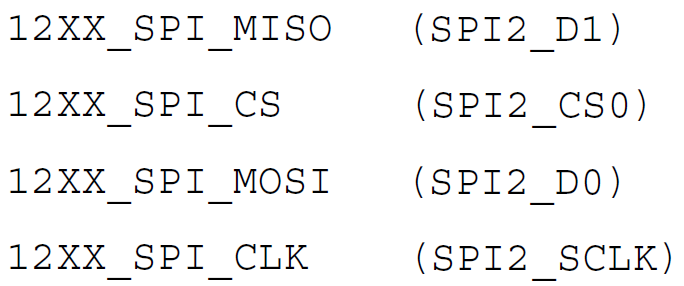
    for SPI2 the connection is the following:

    Is this the same for you?

    The fact that the MOSI voltage drops to 1 V seem to suggest two devices are driving the same line.

    Thanks and Regards,

    Piyali

  • Dear Piyali

    I will describe the memory of SPI pin.

    Thanks and Regards,

    Takahashi

  • Dear Piyali

    Bsp_boardSetPinMux (BSP_DRV_ID_MCSPI, BSP_DEVICE_MCSPI_INST_ID_ 1, BSP_BOARD_MODE_DEFAULT);
    I used the figure just before.

    SPI communication has not been established yet.

    Thanks and Regards,
    Takahashi
  • Dear Piyali

    Previously, MOSI and MISO said they are outputting 3V. However, they seem to be output from the MMIC.
    So it seems like you will not accept signals from TDA side.

    Thanks and Regards,
    Takahashi

  • Hi Takahashi-san

    The MOSI, CS, CLK lines will be output from the TDA (input to AWR) and the MISO would be input to the TDA (output from AWR).

    The pad configuration looks okay.

    As a next step to understand this,
    Can you please place a break point in the function Bsp_ar12xxSpiWriteCb?
    Once you hit this, you can step through the code and check if the GIO_issue and the GIO_reclaim functions run to completion. You would have to put a break point at the instruction after these function calls and give the IPU a run to check this. (Step over may fail as an interrupt has to occur).

    You can also place a break point at mcspiIntrHandler to make sure the interrupt service routine for McSPI is being invoked.

    We can discuss further during the debug call.

    Thanks and Regards,
    Piyali
  • Hi Takahashi-san,

    I am summarizing the result of our debug session here:

    The McSPI interrupt was not getting triggered due to which nothing was being sent out from the MOSI line.
    The McSPI registers between the working and the non-working case was analyzed and it was found:
    File: utils_mcspi.c
    mcspiCfgPrms[mcSPINum].spiHWCfgData.singleOrMultiChEnable has to be set to MCSPI_MULTI_CHANNEL;

    Upon this change, TIJ team confirmed the SPI communication is working at your end.

    Please feel free to close this thread.

    Thanks and Regards,
    Piyali