This thread has been locked.

If you have a related question, please click the "Ask a related question" button in the top right corner. The newly created question will be automatically linked to this question.

RTOS/TDA2PXEVM: MCAN Loopback Example in Processor SDK 03.02

Part Number: TDA2PXEVM

Tool/software: TI-RTOS

Hello,

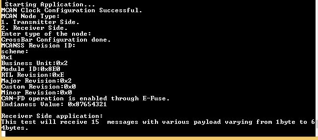
We built the example for MCAN loopback using command "make -s csl_mcan_loopback_app BOARD=tda2px-evm CORE=ipu1_0" and select the transmitter side while executing the example. We want to test internal loopback similar to the DCAN example which works fine.

The loopback example checks for the mode of MCAN at line 607 using api "MCAN_getOpMode"  and waits untill the mode is normal in the file "mcan_evm_loopback_app_main.c". While executing the example, it never comes out of the while loop which checks for the normal mode of the MCAN module. We are using TDA2px-EVM.

Could you please let us know if any settings are to be done for this example as we just built the example and are debugging using JTAG emulator?

Regards,

Amol

  • Hi Amol,

    MCAN sample application does not run in internal loop-back mode like DCAN does. It runs in EVM2EVM loop-back mode. For this you need two boards and connect these boards to a CAN bus. You can just connect CAN_L to CAN_L and CAN_H to CAN_H of the two EVM's CAN Transceiver(as mentioned below).
    After doing above setup, load MCAN sample application on both boards/EVMs. Choose receiver side option on first while transmitter side option on other. MCAN sample application with receiver side option should be run first. Once you do this, application shall run and it will print status accordingly on UART.

    Board connections: Borad1 -> Board2
    J20/DCAN1 pin 3 - > J20/DCAN1 pin 3 (CAN_L)
    J20/DCAN1 pin 4 - > J20/DCAN1 pin 4 (CAN_H)
    J20/DCAN1 pin 5 - > J20/DCAN1 pin 5 (GND)

    Thanks & Regards,
    Vivek Dhande.
    Texas Instruments (India) Pvt Ltd
  • Hello Vivek,

    Thanks for the reply.

    Can we use PCAN and 1 TDA2PX board instead of 2 TDA2PX boards, and use PCAN device as the transmitter side?

    Will the connections be same if PCAN is used?

    Attached are the images of the PCAN device.

    Regards,

    Amol

  • Hello Vivek,

    Could you please let us know if the PCAN device can be used as per the previous post?

    Regards,
    Amol
  • Hi Amol,

    The MCAN application works with two nodes(as I said earlier), one node as Tx while another acting as Rx. Tx node will send 15 CAN-FD messages to Rx node with payload size varying from 1 byte to 64 bytes with fixed predefined message ID. On reception, Rx node then checks for the data. It checks whether sent data is received properly or not and prints status accordingly. So in order to check whether this application has run successfully or not we need prints from both nodes.
    If you want to use PCAN instead of one EVM, you do following:
    1. Connect PCAN CAN_L, CAN_H and GND to same pins of EVM respectively.
    2. Enable PCAN to receive these intended messages.
    3. Run application on EVM with Tx option, it will send 15 messages to PCAN.
    4. Run application on EVM again but with Rx option this time. The MCAN application will wait for these messages.
    5. Send 15 messages from PCAN(received after step 3), in the order of their reception.
    6. The Rx application running on EVM will print status whether it's run was successful or not.

    In this whole process each node will act as Tx as well as Rx in either of the runs.
    You can stop after step 3, but you have to verify the received data(at PCAN side) manually with the Tx data(send by application running on EVM).

    Thanks & Regards,
    Vivek Dhande.
    Texas Instruments (India) Pvt Ltd
  • Hello Vivek,

    Thanks for the reply.

    We are following the steps you mentioned in previous post. However, when we select the EVM with Tx option as mentioned in step 3, it waits in while loop which checks for the normal operation of MCAN module at line 607 of "mcan_evm_loopback_app_main.c" as we stated in the first post.

    Attatching images of the UART prints when Tx option is selected and the screenshot of the while loop checking the mode of MCAN module for our reference.

    Example is continuously checks for the Normal mode of MCAN  module and is in the same while loop, so no transmission of messages takes place.

    Could you please let us know what could be the possible issue?

    Regards,

    Amol

  • Hi Amol,

    When you are running example on IPU core, can you also run primary core i.e. A15. If A15 is not used in your application please put it in free run mode.
    Please run A15 prior to running MCAN application.


    Thanks & Regards,
    Vivek Dhande.
    Texas Instruments (India) Pvt Ltd

  • Hi Vivek,

    Thanks for the reply.

    The MCAN module was set to Normal opration mode when A15 core was set to free run mode.

    However, we are not able to transmit the data and are observing following prints on UART that shows the transmission was not successful.

    We have also tried the application to run in Receiver mode. We send some dummy data from the PCAN device and observed that the application has not invoked the ISR for receiving the messages and waits in the while loop. Following are the UART prints observed.

    Could you please let us know if there are any more settings / configurations to be done ?

    Regards,

    Amol

  • Hello Vivek,

    Could you please let us know about the settings / configuration  to be done for the above post?

    Also, we tried the internal and external dcan loopback example, Internal loopback example works but the External loopback is showing following prints on UART.

    Please let us know about this.

    For your information, we are now using the Processor SDK 03.03.00.00 version and are facing the exact same issues for MCAN and DCAN as stated above.

    Regards,

    Amol

  • Hi Amol,

    For MCAN application, can you check following:

    1. Connections(mentioned in my earlier reply) are proper and firm.

    2. Make sure TDA2Px MCAN and PCAN have same bit rates. MCAN on TDA2Px is configured for 1 Mbps Arbitration Phase bit rate and 5 Mbps as Data Phase bit rate.


    Thanks & Regards,
    Vivek Dhande.
    Texas Instruments (India) Pvt Ltd

  • Hello Vivek,

    Thanks for the reply.
    We checked both the conditions you mentioned:
    1. Connections are good
    2. PCAN is also set to the required data rate.

    Please let us know if we can check for any other configuration / setting / connections.

    Regards,
    Amol
  • Hi Amol,

    For MCAN application, Can you capture MCAN register dump when application is running in Tx mode after failure?
    You can put break-point in the ISR and then capture the register dump.


    Thanks & Regards,
    Vivek Dhande.
    Texas Instruments (India) Pvt Ltd
  • Hello Vivek,

    We have put the breakpoint as you said in the ISR when running with Transmit mode. We could not see any MCAN registers in the list.

    Attaching the register dump and the screenshot. 

    can_reg_dump.txt
    521177 14
    R PC 0x0000000B 0x84042BB8
    R SP 0x0000000B 0x8401FEF8
    R LR 0x0000000B 0x840434D7
    R xPSR 0x0000000B 0x6100004E
    R R0 0x0000000B 0x00000002
    R R1 0x0000000B 0x4806A000
    R R2 0x0000000B 0xFFFFFF0A
    R R3 0x0000000B 0x62C00000
    R R4 0x0000000B 0x00000000
    R R5 0x0000000B 0x00000000
    R R6 0x0000000B 0x00000000
    R R7 0x0000000B 0x84020000
    R R8 0x0000000B 0x00000000
    R R9 0x0000000B 0x00000000
    R R10 0x0000000B 0x00000000
    R R11 0x0000000B 0x00000000
    R R12 0x0000000B 0x8401FEA8
    R R13 0x0000000B 0x8401FEF8
    R R14 0x0000000B 0x840434D7
    R MSP 0x0000000B 0x8401FEF8
    R PSP 0x0000000B 0x00000000
    R DSP 0x0000000B 0x00000000
    R CTRL_FAULT_BASE_PRI 0x0000000B 0x00000000
    R IPU1_C0_RW_TABLE_CORTEXM4_RW_PID1 0x0000000B 0x00000000
    R IPU1_C0_RW_TABLE_CORTEXM4_RW_PID2 0x0000000B 0x00000000
    

    Is the MCAN registers visible when the breakpoint in ISR is struck? Or do we have to add the MCAN registers in the list? If yes, what is to be done for adding the MCAN registers in CCS ?

    Regards,

    Amol

  • Hello Vivek,

    As posted in some previous posts, we are receiving the "Interrupt Status 0x10000000" from the transmit ISR on the UART and are unable to transmit data.

    We have found that this value of interrupt status points to the "PED" bit of MCAN_IR register.

    We have also tried connecting 2 EVM's as you have stated in the post with connection details between 2 EVM's.

    Could you please let us know what could be the possible issue and what is to be done for this issue ?

    Regards,

    Amol

  • Hello Vivek,

    We added some debug prints into the MCAN loopback example and have following prints on UART,

    1] protocol status -> lastErrorCode = 0x7
    2] protocol status -> act = 0x1
    3] protocol status -> errPassive = 0x1
    4] protocol status -> warningStatus = 0x1
    5] protocol status -> busOffStatus = 0x0
    6] protocol status -> resi = 0x0
    7] protocol status -> rbrf = 0x0
    8] protocol status -> rfdf = 0x0
    9] protocol status -> pxe = 0x0
    10] protocol status -> tdcv = 0x10
    11] protocal status -> dlec = 0x3
    and
    12] interrupt status = 0x10000000 as stated in previous post.

    Could you please let us know what is to be done for this issue ?
    Also let us know if you require any other input from us.

    Regards,
    Amol
  • Hello Vivek,

    Just to update, the UART prints in the above post are after the Interrupt status error is received in the Transmission mode and we do not get anything on the receiving node.

    Regards,
    Amol
  • Hi Amol,

    To get the MCAN register dump, open the memory browser(go to View->Memory Browser) and go to '0x62C00000' address. And then take the dump of the registers.

    I'll will be able to comment only after looking at these register values.


    Thanks & Regards,
    Vivek Dhande.
    Texas Instruments (India) Pvt Ltd
  • Hello Vivek,

    Sharing the register dump of MCAN. We have 2 instances of dump in "App_mcanIntr0ISR()".

    First instance at "MCAN_clearIntrStatus" call.

    617.dat

    Second instance at "UARTConfigPuts" call in the else statement.

    627.dat

    Please let us know if you require any other dumps.

    Regards,

    Amol

  • Hi Amol,

    Thanks for sharing the register dump.
    By looking at the register dump, looks like you are getting ACK error for sent CAN FD frame/message. This error will typically happen when sent message is not accepted/ACKed by any other node on the CAN bus.
    Can you please check that you are configuring a filter at PCAN side to receive the message sent by TDA2Px(with Standard ID of 0x4)?


    Thanks & Regards,
    Vivek Dhande.
    Texas Instruments (India) Pvt Ltd
  • Hello Vivek,

    Thanks for the reply.
    We were using PCAN device, however as there were issues, we have posted that we are now using 2 EVM's and connections are done as posted by you. The register dumps provided are also when one EVM is in Receiver mode and other is in Transmitter mode.

    Regards,
    Amol
  • Hi Amol,

    Can you refer these instructions: processors.wiki.ti.com/.../PDK_TDA_CSL_User_Guide ?
    Just make sure you are following all steps present on the above page/section.
    Also, can you send me the pictures of the connections?


    Thanks & Regards,
    Vivek Dhande.
    Texas Instruments (India) Pvt Ltd
  • Hello Vivek,

    Yes, we have refered the CSL_User_Guide. All the steps mentioned are followed.

    Sharing you the connections diagrams.

    DCAN1(J20 of EVM1) -> DCAN1(J20 of EVM2)

    J20->3 -> J20->3

    J20->4 -> J20->4

    J20->5 to J20->5

    Please let us know if we can have a debug session.

    Regards,

    Amol

  • Hi Amol,

    From the provided snapshots, looks like you have connected them wrongly.

    You have connections like:

    J20->5 -> J20->5

    J20->7 -> J20->7

    J20->9 to J20->9

    J20 layout is like:

    Please connect by referring above image of J20 connector.

    Thanks & Regards,

    Vivek Dhande.

    Texas Instruments (India) Pvt Ltd

  • Hello Vivek,

    Thanks for your support. We can now test the example successfully.

    Regards,
    Amol