This thread has been locked.

If you have a related question, please click the "Ask a related question" button in the top right corner. The newly created question will be automatically linked to this question.

AM335x RESETIN_OUT pin

Other Parts Discussed in Thread: AM3352, TPS65251, TPS3823, TPS386000

"Caution must be used when implementing the nRESETIN_OUT as an bi-directional reset signal. Because of the short maximum time allowed using RSTTIME1, it does not supply an adequate debounce time for an external push button circuit. The processor could potentially start running while external components are still in reset. It is recommended that this signal be used as input only (do not connect to other devices as a reset) to implement a push button reset circuit to the AM335x, or an output only to be able to reset other devices after an AM335x reset completes."

Above paragraph is last para of 8.1.1.7.4.1 section of  AM335x TRM.

When we use push button for warmreset push button will give a reset pulse of milisec but befor completion of that pulse AM335x start asserting it own pulse outwards. We think that that would cause electrical problem and also there is chance of chip damage.

We would like to know are the I/O buffers of AM335x can  handle all this for long time?

Please reply it is urgent!!!!!!!!

  • The internal nRESETIN_OUT signal  connects to the WARMRSTn terminal and is configured as an input and open-drain output.

    The following description can be found in the Warm Reset Input/Reset Output (nRESETIN_OUT) section of the TRM.

    The nRESETIN_OUT output buffer is configured as an open-drain; consequently, an external pull-up resistor is required.

    Therefore, all external sources should also be open-drain.

    Regards,
    Paul

  • Hi Paul,

    TRM describes:

    "Note: It is recommended to implement warm reset as an input only (for example, push button) or an output only (to reset external peripherals), not both."

    Why is implementing both not recommended?

    Best regards,

    Daisuke


  • The PWRONRSTn terminal is connected to an internal reset input signal via the PWRONRSTn input buffer and internal reset output signal via the PWRONRSTn output buffer.   There is a circuit inside AM335x that detects the falling edge of the reset input signal and applies reset to the internal circuits, asserts the reset output signal, and starts a timer that extends reset for a period defined by the PRCM.PRM_RSTIME register.  The timer is used to hold reset low for a specific period of time without any qualification from the reset input because reset would be permanently latched low if the input was used as a qualifier for releasing the output.  The default value of the PRCM.PRM_RSTIME register is very small and the master oscillator (OSC0) is used to source the timer which causes the reset time to be very short.

    In some cases, using the terminal as input and output may create a situation where peripheral devices connected to the AM335x PWRONRSTn terminal are still being held in reset by another reset source when the reset timer described above expires and AM335x begins executing code.  One such example may be a product that connects the reset input of an Ethernet PHY to the PWRONRSTn terminal and also connected a push-button to ground.  If someone presses the push-button and holds it too long, the Ethernet PHY may still be held in reset when AM335x code attempts to initialize it.

    Using the PWRONRSTn terminal as input only or output only eliminates the situation described above.

    Regards,
    Paul

  • Hi Paul,

    Thank you for your reply.

    When the peripheral devices connected to the nRESETIN_OUT terminal are still being held in reset by another reset source, are the AM335x still not being held in reset?

    You describes on the other thread:

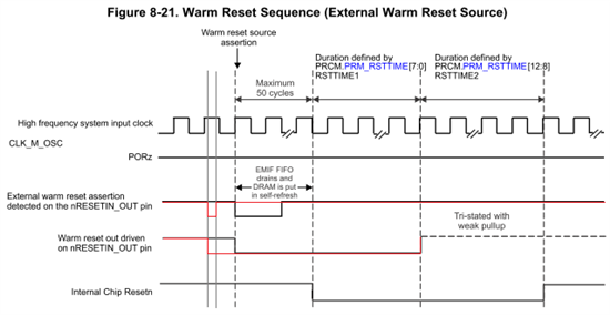
    "If the external warm reset source is driving the WARMRSTn terminal when this time elapses, AM335x will stop driving the WARMRSTn terminal low and the RSTTIME2 counter will pause until the external source stops driving the WARMRSTn terminal low."

    http://e2e.ti.com/support/arm/sitara_arm/f/791/t/226275.aspx

    Best regards,

    Daisuke


  • Yes, my explanation in the other forum post is correct.  Thanks for reminding me about the other post.  I had forgotten about the RSTTIME2 counter being stalled until the external reset source is released.  However, there still may be cases where using the WARMRSTn terminal as an input and output can cause problems.  The most likely case is when a simple push-button switch is being used as an external reset source.  There could be an issue if someone held the push-button long enough for the RSTTIME1 timer to expire and the push-button contacts bounced on release such that the WARMRSTn signal went low enough to generate a short invalid reset pulse to the peripheral devices but not low enough to re-trigger the AM335x reset circuit.  In this case, the peripheral device may receive this short invalid reset pulse and enter an unknown state while the AM335x device begins executing code that is not able to communicate with this peripheral device since it is in an unknown state.  This may not be a problem if the external source doesn’t generate invalid short reset pulses.

    Regards,
    Paul

  • Hi Paul,

    Thank you for your reply.

    Some inputs and open-drain outputs on the peripheral devices connect to the nRESETIN_OUT pin, any push-button switch not connect.

    Our customer will check that the external source doesn't generate invalid short reset pulses .

    Best regards,

    Daisuke


  • Hi Paul,

    In the duration defined by RSTTIME2, can the warm reset sequence begin again when the WARMRSTn terminal makes a transition from a valid high logic level to a valid low logic level?

    Best regards,
     
    Daisuke


  • If the WARMRSTn terminal is not being driven low by an external source when RSTTIME1 expires, AM335x will stop driving WARMRSTn which allows the external pull-up to pull the signal high.  If the signal is driven low again by an external source before RSTTIME2 expires, the internal chip reset will never be released and the warm reset process starts over.

    Regards,
    Paul 

  • Hi Paul,

    Thank you for your reply.

    I have other question.

    Is the minimum pulse width for external warm reset assertion a width of one CLK_M_OSC clock period?

    I understand that the WARMRSTn terminal is driven low by the warm reset output at a rising edge of CLK_M_OSC clock after the WARMRSTn terminal is driven low by an external source.

    Best regards,

    Daisuke


  • The reset inputs are applied to the internal circuits asynchronous and released synchronous to he clock, so the reset low period can be very short.

    Regards,
    Paul

  • Hi Paul,

    Thank you for your reply.

    I understand that the minimum pulse width is not defined and that the following sequence is possible.

    Is my understanding correct?

    Best regards,

    Daisuke

  • I'm not sure what you are trying to show with this modified sequence.

    The AM335x will begin driving the WARMRSTn terminal low with a short asynchronous delay after the external source drives WARMRSTn low.  The synchronous portion of the sequence will begin at the same time, so the vertical dashed line used to indicate "Warm reset source assertion" would need to be shifted to the left to align with the falling edge of the pulse you drew.

    Regards,
    Paul


  • Hi Paul,
     
    Thank you for your reply.
     
    Could you tell me the maximum delay that the AM335x begins driving the WARMRSTn terminal low after an external source drives WARMRSTn terminal low?

    Best regards,
     
    Daisuke


  • It is not possible for us to measure this short asynchronous delay, because the external source is still driving the WARMRSTn terminal low when the AM335x output begins driving it low.  Therefore, this parameter is not characterized and published in the data sheet.

    Regards,
    Paul

  • Hi Paul,
     
    Thank you for your reply.
     
    I understand that the minimum pulse width can not be defined. Can you tell me the recommended pulse width?
     
    Best regards,
     
    Daisuke


  • Hi Paul

    I connect the watchdog output (the /RESET1 of the TPS38600 ) to the WARMRSTn terminal. And I connect the reset of the ethernet phy to the WARMRSTn terminal.

    Are there any problem?


    Thank you

  • I'm not sure how your question is directly related to this forum thread without understanding more details.  However, I think your question may be related to the another E2E post.  Please read https://e2e.ti.com/support/arm/sitara_arm/f/791/p/335939/1172185#1172185

    If you connect another device than can drive WARMRSTn low during power-up, you would need to insert a series current limiting resistor on the WARMRSTn terminal as shown in the post referenced above.

    What is sourcing the PWRONRSTn input terminal?  You need to make sure the PWRONRSTn input is held low until all power supplies are valid.  Therefore, I would have expected voltage supervisors outputs to be connected to PWRONRSTn rather than WARMRSTn.

    Regards,
    Paul

  • Hi paul

    I have two Am3352 in my board.

    The source of the PWRONRSTn input terminal is the PGOOD of the TPS65251 and the voltage supervisors output of the TPS38600。I connect the PWRONRSTn of the two am3352 together.

    The two am3352 have two independent watch dog( one is TPS38600,the other is TPS3823).The watchdog output of the TPS38600 is connected to the WARMRSTn of the first am3352. The watchdog output of the TPS3823 is connected to the WARMRSTn of  the second am3352.

    If I connect the watchdog output to PWRONRSTn,I can not have  independent watch dog.

    Is there other solution?

    ReGards

    zuobing huang

  • I was not able to find a device TPS38600. My reply yesterday was based on the assumption your reference to TPS38600 was meant to be TPS386000. Did you mean TPS386000 rather than TPS38600?

    My concern related to connecting voltage supervisor outputs to PWRONRSTn was based on your previous post that mentioned plans to connect /RESET1 to the WARMRSTn. The /RESET1 output of the TPS386000 is connected to a voltage supervisor, not the watchdog. The watchdog output is /WDO.

    I do not see a problem with using independent watchdogs connected to each AM335x WARMRSTn terminal as long as you insert a series current limiting resistor on the WARMRSTn terminal if the watchdog output could drive low while power is applied to AM335x. Did you read the other E2E forum thread and understand the issue described there?

    Regards,
    Paul
  • Dear Paul:

    Sorry I use TPS386000.I make a mistake.

    SCHEMATIC1 _ Page 15_ MMI-USB.pdf

    I connect /WDO to /MR.So the /RESET1 output of the TPS386000 is the watchdog output.

    Thank your help.

    I have no problem.