This thread has been locked.

If you have a related question, please click the "Ask a related question" button in the top right corner. The newly created question will be automatically linked to this question.

why timer2,4,5,7 could enable in uboot, timer 3,6 couldn't?

Hi all
I am using TI platform for AM335x, with Am335x EVM Board, download SDK from the following URL
http://software-dl.ti.com/sitara_linux/esd/AM335xSDK/06_00_00_00/index_FDS.html


I'm trying to enable the timer2~7 using the following code, and the result shows the timer3 and timer6 couldn't enable succeed (cmper->timer3clkctrl & cmper->timer6clkctrl) but timer2,4,5,7 could . I feel confused, does anyone know what's wrong with my code :-(

/*
 * Force power domain wake up transition
 * Ensure that the corresponding interface clock is active before
 * using the peripheral
 */
static void power_domain_wkup_transition(void)
{
	writel(PRCM_FORCE_WAKEUP, &cmper->l3clkstctrl);
	writel(PRCM_FORCE_WAKEUP, &cmper->l4lsclkstctrl);
	writel(PRCM_FORCE_WAKEUP, &cmwkup->wkclkstctrl);
	writel(PRCM_FORCE_WAKEUP, &cmper->l4fwclkstctrl);
	writel(PRCM_FORCE_WAKEUP, &cmper->l3sclkstctrl);

	//Enable the domain power state for Timer2~7
	writel(0x1 << 13, &cmper->l4lsclkstctrl);/*Timer 7*/
	writel(0x1 << 28, &cmper->l4lsclkstctrl);/*Timer 6*/
	writel(0x1 << 27, &cmper->l4lsclkstctrl);/*Timer 5*/
	writel(0x1 << 16, &cmper->l4lsclkstctrl);/*Timer 4*/
	writel(0x1 << 15, &cmper->l4lsclkstctrl);/*Timer 3*/
}

/*
 * Enable the peripheral clock for required peripherals
 */
static void enable_per_clocks(void)
{
	/* Enable the control module though RBL would have done it*/
	writel(PRCM_MOD_EN, &cmwkup->wkctrlclkctrl);
	while (readl(&cmwkup->wkctrlclkctrl) != PRCM_MOD_EN)
		;

	/* Enable the module clock */
	writel(PRCM_MOD_EN, &cmper->timer7clkctrl);
	while (readl(&cmper->timer7clkctrl) != PRCM_MOD_EN)
		;

	/* Select the Master osc 24 MHZ as Timer7 clock source */
	writel(0x1, &cmdpll->clktimer7clk);

	/* Enable the module clock */
	writel(PRCM_MOD_EN, &cmper->timer2clkctrl);
	while (readl(&cmper->timer2clkctrl) != PRCM_MOD_EN)
		;

	/* Select the Master osc 24 MHZ as Timer2 clock source */
	writel(0x1, &cmdpll->clktimer2clk);


	/* Enable the module clock */
	writel(PRCM_MOD_EN, &cmper->timer3clkctrl);
	while (readl(&cmper->timer3clkctrl) != PRCM_MOD_EN)
		;

	/* Select the Master osc 24 MHZ as Timer3 clock source */
	writel(0x1, &cmdpll->clktimer3clk);

	/* Enable the module clock */
	writel(PRCM_MOD_EN, &cmper->timer4clkctrl);
	while (readl(&cmper->timer4clkctrl) != PRCM_MOD_EN)
		;

	/* Select the Master osc 24 MHZ as Timer4 clock source */
	writel(0x1, &cmdpll->clktimer4clk);

	/* Enable the module clock */
	writel(PRCM_MOD_EN, &cmper->timer5clkctrl);
	while (readl(&cmper->timer5clkctrl) != PRCM_MOD_EN)
		;

	/* Select the Master osc 24 MHZ as Timer5 clock source */
	writel(0x1, &cmdpll->clktimer5clk);

	/* Enable the module clock */
	writel(PRCM_MOD_EN, &cmper->timer6clkctrl);
	while (readl(&cmper->timer6clkctrl) != PRCM_MOD_EN)
		;

	/* Select the Master osc 24 MHZ as Timer6 clock source */
	writel(0x1, &cmdpll->clktimer6clk);

        ....
        ....
        ....
}

/*
 * Configure the PLL/PRCM for necessary peripherals
 */
void pll_init()
{
	/* Start at 550MHz, will be tweaked up if possible. */
	mpu_pll_config(MPUPLL_M_300);
	core_pll_config(OPP_50);
	per_pll_config();

	/* Enable the required interconnect clocks */
	enable_interface_clocks();

	/* Power domain wake up transition */
	power_domain_wkup_transition();

	/* Enable the required peripherals */
	enable_per_clocks();
}

  • Hi,

    As far as I remember Timers 3 and 6 are used in the Ethernet CPSW driver.

  • Hi, Biser

    Thanks for your reply :-)

    You mean if I wanna enable timer 3 and timer6, I should also enable the Ethernet module in uboot? Is that right?

  • No, what I meant is that you should check that your code doesn't get overwritten somewhere.

  • Hi Biser

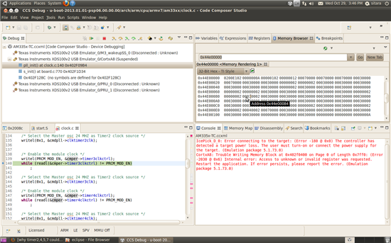
    I only modified the enable_per_clocks() and power_domain_wkup_transition() function under s_init()->pll_init(), and the CCS debugger from XDS100 v2 always stay in infinite while loop because of while (readl(&cmper->timer6clkctrl) != PRCM_MOD_EN) , so the Ethernet module haven't initialized(the Ethernet module initialize code is after the timer 6), if the Ethernet module haven't initialized, why the timer6 and timer3 couldn't enable? That why I'm confuse here :-(


    /*
     * Enable the peripheral clock for required peripherals
     */
    static void enable_per_clocks(void)
    {
    	/* Enable the control module though RBL would have done it*/
    	writel(PRCM_MOD_EN, &cmwkup->wkctrlclkctrl);
    	while (readl(&cmwkup->wkctrlclkctrl) != PRCM_MOD_EN)
    		;
    
    	/* Enable the module clock */
    	writel(PRCM_MOD_EN, &cmper->timer7clkctrl);
    	while (readl(&cmper->timer7clkctrl) != PRCM_MOD_EN)
    		;
    
    	/* Select the Master osc 24 MHZ as Timer7 clock source */
    	writel(0x1, &cmdpll->clktimer7clk);
    
    	/* Enable the module clock */
    	writel(PRCM_MOD_EN, &cmper->timer2clkctrl);
    	while (readl(&cmper->timer2clkctrl) != PRCM_MOD_EN)
    		;
    
    	/* Select the Master osc 24 MHZ as Timer2 clock source */
    	writel(0x1, &cmdpll->clktimer2clk);
    
    
    	/* Enable the module clock */
    	writel(PRCM_MOD_EN, &cmper->timer3clkctrl);
    	while (readl(&cmper->timer3clkctrl) != PRCM_MOD_EN)/*The debugger is getting stuck in here*/
    		;
    
    	/* Select the Master osc 24 MHZ as Timer2 clock source */
    	writel(0x1, &cmdpll->clktimer3clk);
    
    	/* Enable the module clock */
    	writel(PRCM_MOD_EN, &cmper->timer4clkctrl);
    	while (readl(&cmper->timer4clkctrl) != PRCM_MOD_EN)
    		;
    
    	/* Select the Master osc 24 MHZ as Timer2 clock source */
    	writel(0x1, &cmdpll->clktimer4clk);
    
    	/* Enable the module clock */
    	writel(PRCM_MOD_EN, &cmper->timer5clkctrl);
    	while (readl(&cmper->timer5clkctrl) != PRCM_MOD_EN)
    		;
    
    	/* Select the Master osc 24 MHZ as Timer2 clock source */
    	writel(0x1, &cmdpll->clktimer5clk);
    
    	/* Enable the module clock */
    	writel(PRCM_MOD_EN, &cmper->timer6clkctrl);
    	while (readl(&cmper->timer6clkctrl) != PRCM_MOD_EN)
    		;
    
    	/* Select the Master osc 24 MHZ as Timer2 clock source */
    	writel(0x1, &cmdpll->clktimer6clk);


    	/* UART0 */
    	writel(PRCM_MOD_EN, &cmwkup->wkup_uart0ctrl);
    	while (readl(&cmwkup->wkup_uart0ctrl) != PRCM_MOD_EN)
    		;
    
    	/* UART1 */
    #ifdef CONFIG_SERIAL2
    	writel(PRCM_MOD_EN, &cmper->uart1clkctrl);
    	while (readl(&cmper->uart1clkctrl) != PRCM_MOD_EN)
    		;
    #endif /* CONFIG_SERIAL2 */
    
    	/* UART2 */
    #ifdef CONFIG_SERIAL3
    	writel(PRCM_MOD_EN, &cmper->uart2clkctrl);
    	while (readl(&cmper->uart2clkctrl) != PRCM_MOD_EN)
    		;
    #endif /* CONFIG_SERIAL3 */
    
    	/* UART3 */
    #ifdef CONFIG_SERIAL4
    	writel(PRCM_MOD_EN, &cmper->uart3clkctrl);
    	while (readl(&cmper->uart3clkctrl) != PRCM_MOD_EN)
    		;
    #endif /* CONFIG_SERIAL4 */
    
    	/* UART4 */
    #ifdef CONFIG_SERIAL5
    	writel(PRCM_MOD_EN, &cmper->uart4clkctrl);
    	while (readl(&cmper->uart4clkctrl) != PRCM_MOD_EN)
    		;
    #endif /* CONFIG_SERIAL5 */
    
    	/* UART5 */
    #ifdef CONFIG_SERIAL6
    	writel(PRCM_MOD_EN, &cmper->uart5clkctrl);
    	while (readl(&cmper->uart5clkctrl) != PRCM_MOD_EN)
    		;
    #endif /* CONFIG_SERIAL6 */
    
    	/* GPMC */
    	writel(PRCM_MOD_EN, &cmper->gpmcclkctrl);
    	while (readl(&cmper->gpmcclkctrl) != PRCM_MOD_EN)
    		;
    
    	/* ELM */
    	writel(PRCM_MOD_EN, &cmper->elmclkctrl);
    	while (readl(&cmper->elmclkctrl) != PRCM_MOD_EN)
    		;
    
    	/* MMC0*/
    	writel(PRCM_MOD_EN, &cmper->mmc0clkctrl);
    	while (readl(&cmper->mmc0clkctrl) != PRCM_MOD_EN)
    		;
    
    	/* i2c0 */
    	writel(PRCM_MOD_EN, &cmwkup->wkup_i2c0ctrl);
    	while (readl(&cmwkup->wkup_i2c0ctrl) != PRCM_MOD_EN)
    		;
    
    	/* gpio1 module */
    	writel(PRCM_MOD_EN, &cmper->gpio1clkctrl);
    	while (readl(&cmper->gpio1clkctrl) != PRCM_MOD_EN)
    		;
    
    	/* gpio2 module */
    	writel(PRCM_MOD_EN, &cmper->gpio2clkctrl);
    	while (readl(&cmper->gpio2clkctrl) != PRCM_MOD_EN)
    		;
    
    	/* gpio3 module */
    	writel(PRCM_MOD_EN, &cmper->gpio3clkctrl);
    	while (readl(&cmper->gpio3clkctrl) != PRCM_MOD_EN)
    		;
    
    	/* i2c1 */
    	writel(PRCM_MOD_EN, &cmper->i2c1clkctrl);
    	while (readl(&cmper->i2c1clkctrl) != PRCM_MOD_EN)
    		;
    
    	/* Ethernet *//*Ethernet is after the timer initialize*/
    	writel(PRCM_MOD_EN, &cmper->cpgmac0clkctrl);
    	while ((readl(&cmper->cpgmac0clkctrl) & CPGMAC0_IDLE) != PRCM_FUNCTL)
    		;
    
    	/* spi0 */
    	writel(PRCM_MOD_EN, &cmper->spi0clkctrl);
    	while (readl(&cmper->spi0clkctrl) != PRCM_MOD_EN)
    		;
    
    	/* RTC */
    	writel(PRCM_MOD_EN, &cmrtc->rtcclkctrl);
    	while (readl(&cmrtc->rtcclkctrl) != PRCM_MOD_EN)
    		;
    
    	/* MUSB */
    	writel(PRCM_MOD_EN, &cmper->usb0clkctrl);
    	while (readl(&cmper->usb0clkctrl) != PRCM_MOD_EN)
    		;
    
    
    }


  • If it gets stuck in this loop this means that the peripheral module functional clock is not provided.

  • Please disregard my last post. I was thinking about timer module registers, while this is PRCM module register.

  • This might cause a problem:

    while (readl(&cmper->timer3clkctrl) != PRCM_MOD_EN);

    Can you check what is actually read from timer3clkctrl? It might be different from PRCM_MOD_EN and still be correct.

  • Hi, Biser

    Sorry for late reply. The value read from cmper->timer3clkctrl is 0x30002

  • I really don't know what's happening. The "3" indicates that the module is disabled.