This thread has been locked.

If you have a related question, please click the "Ask a related question" button in the top right corner. The newly created question will be automatically linked to this question.

AM3359 Cortex-A8 WFI instruction does not cause PRCM_M3_IRQ2

Other Parts Discussed in Thread: AM3359, SYSCONFIG

According to the sleep sequencing for the AM3359, when you execute the WFI command from SRAM the PRCM_M3_IRQ2 interrupt will signal the Cortex-M3. You can see this progression in the state flow diagram at http://processors.wiki.ti.com/index.php/File:SA_deep_sleep_state_flow.JPG. When the M3 receives this interrupt, the interrupt handler function "extint34_handler" should execute since it is registered to this interrupt in the vector table. However, this never happens.

I have compiled the CM3 PM firmware sources from http://arago-project.org/git/projects/?p=am33x-cm3.git;a=summary and loaded/initialized the CM3 with the bin file successfully. I am also using an XDS100v2 JTAG emulator to connect to the M3 core and I am able to step through the code and use breakpoints. When I set a breakpoint in the interrupt handler for #34, it never hits the breakpoint, which tells me the A8 never signals it at WFI.

Up until the WFI command is executed, I am able to communicate with the firmware on the M3; it is possible to send the DS0/STANDBY commands and it acknowledges them successfully. For the A8 to signal the M3 correctly, what settings are required for this interrupt to be generated? Should it happen unconditionally, or does the A8 internally check clock settings/ power domain settings?

  • Hi Geoff,

    I will forward this to the factory team.

  • There are low power mode demo programs and source codes in AM335x StarterWare. Please check the sleep sequence for DeepSleep0 and see if you are missing something in your sleep sequence.

    AM335x StaterWare: www.ti.com/.../starterware-sitara.

    Power Management Source code location
    ..\AM335X_StarterWare_02_00_01_01\examples\evmAM335x\demo\demoPwrMgmnt.c

    Low power mode entry function
    void PowerSaveModeEnter(deepSleepData dsData, unsigned int slpMode)

    StarterWare Power Management Wiki
    processors.wiki.ti.com/.../AM335x_StarterWare_Power_management

  • Hello Kazunobu-san,

    Thank you for the example. I have been reviewing the Arago linux project's suspend sequence (am33xx_pm_suspend) against my code. So far, I have verified most of the steps have been taken to bring the device to the required power state before executing WFI. I will use the demo example you provided to check against since it is a bit more straightforward than the linux code.

    Are all of the steps in the power down sequence (http://processors.wiki.ti.com/index.php/AM335x_StarterWare_Power_managementup until WFI required for the PRCM_M3_IRQ2 interrupt to be generated, or will it be generated regardless of these steps? 

    Thank you,

    Geoff Wright

  • Hi Geoff,
    Some of steps are for resume and power optimizations so those are not necessary to just generate PRCM_M3_IRQ2 but will be required for proper suspend/resume operation. Please make sure that there is no pending interrupt for A8 before executing WFI. If there is a pending interrupt, WFI won't generate PRCM_M3_IRQ2.
  • In addition to what Shin stated, you must also make sure that CM_MPU_MPU_CLKCTRL has it's MODULEMODE bits set to 0, otherwise WFI acts as a normal wait-for-interrupt instruction and does not generate any interrupt. That is the requirement for PRCM_M3_IRQ2 to be generated.

  • I was able to get the debugger to hit the breakpoint in the CM3 firmware for the DS0 pm handler by following your suggestions. the MPU MODULEMODE was not getting set to 0 and the M3_TXEV interrupt (irq 78) was firing again leaving it pending. This was waking the A8 back up immediately and not having the MPU mode disabled was preventing the PRCM_M3_IRQ2 interrupt from triggering the CM3. So I masked all interrupts before executing WFI. Stepping through the ds0 command handler, I see it disabling the domains and clock before finishing the power down.

    However, now I cannot get the device to wake up. I set the wake up mask to "WAKE_SOURCES_ALL" in the initial DS0 IPC command, but none of the valid wake up sources appear to be trigger the resume process. Is there a way I can use the JTAG to debug whether the wakeup handler is actually being called in the CM3 firmware?

    Thank you.

  • Sounds like some good progress. My first suggestion would be place code like

    volatile int x = 0x12341234;
    
    while (x);

    in your resume function in the CM3 firmware and then disconnect from JTAG while trying to debug this, JTAG can cause unpredictable behavior during DeepSleep0. You should be able to connect to the CM3 and verify that you have reached the loop point and then move on from there. You should be able to spot the 0x12341234 value in a register with JTAG and change it to zero to cause the infinite loop to bail out and allow you to continue execution.

    Which wake source are you trying to use to wake the system? In order for the possible IPs to generate a wake interrupt, the corresponding CLKCTRL register for that IP in the PRCM must be set to 0 (IDLE) after configuring them. Otherwise they will not generate a wake interrupt and your system will remain in DeepSleep0 state.

  • Hello Dave,

    I am trying to wake the CM3 with a button that is connected on GPIO0_27. Before jumping to my WFI routine in SRAM I set CM_WKUP_GPIO0_CLKCTRL to (2 << 16)|(2 < 0) to enable the module and set it to smart idle. It's value before suspending is (0x00020002).

    In the CM3 PM firmware I have modified the a8_wake_ds0_handler() to call while(x) like you suggested at the end of the function. However, I do not see the power consumption jump back up when I press the button. It is also not possible to connect to the M3 with the XDS100v2 at this point. It keeps giving me the error: 

    Error connecting to the target:
    (Error -5009 @ 0x0)
    Unable to access the DAP. Reset the device, and retry the operation. If error persists, confirm configuration, power-cycle the board, and/or try more reliable JTAG settings (e.g. lower TCLK).
    (Emulation package 0.0.0.0)

    I have tried power cycling the XDS100 and restarting CCSv5 (this is sometimes necessary when using the XDS100 as it doesn't seem to work perfectly), but I always get this message. WAKE_SOURES_ALL is set to 0x1FFF so GPIO0 should be able to wake it up. Any ideas?


    Thank you.

  • IDLEMODE in GPIO_SYSCONFIG should be set to 3h = Smart Idle Wakeup (GPIO0 only). Otherwise, GPIO0 wakeup event cannot be generated.
    Please also monitor master oscillator on oscilloscope and confirm it goes off in suspend and comes back after GPIO0 wakeup event.
  • I set the SYSCONFIG register at (0x44E07000+0x10) to ((3 << 3)|(1 << 2)) to get GPIO0 to smart idle as you recommended but I am still not able to observe any wake up behavior from the CM3. I connected SYSBOOT5 high to enable CLKOUT1 and remuxed it so I could see the master oscillator with the oscilloscope. I am able to see the clock get disabled when the CM3 gets the PRCM_M3_IRQ2 signal, but when I press the GPIO0_27 button the clock does not come back. Is there anything else I can try?

    Thank you,
    Geoff
  • >>I have tried power cycling the XDS100 and restarting CCSv5 (this is sometimes necessary when using the XDS100 as it doesn't seem to work perfectly),

    Just as a datapoint, I have been able to run to a BP in CCSv5 at the WFI and then step/resume after that (but it has been a couple of years).   The attached archived screenshot looks like it was done on an EVM-SK with built-in XDS100v2 (and pretty sure it was CCSv5.3 and SDK05.06).  Pretty sure I had also used an external XDS510 on an AM335x EVM to do the same thing. 

    Have not run it recently (though I believe I had better luck with Win7 CCS than Linux.  You can load the symbols from the vmlinux file in Win7 CCS no problem)

  • Can you see the master oscillator at XTALOUT pin ? This signal is direct output from the master oscillator and should be off in successful suspend and come back on wakeup event.

    Which board are you using ? 

  • Hi,

    Just to go back to a previous point quickly, I apologize if I wasn't clear that the CLKCTRL of the module must be set to off and the module must be disabled in order to wake the SoC from sleep. I know this seems backwards, but it is reuiqred that you configure the module for wake and THEN disable it in order for a wakeup from DeepSleep event to be generated. So this means rather than 0x00020002 you want the value of the CLKCTRL (0x44e00408 for GPIO0) to be 0x00030000, which you can accomplish by writing a 0 to the entire register because the IDLEST bits (which are 3 here) are read only.

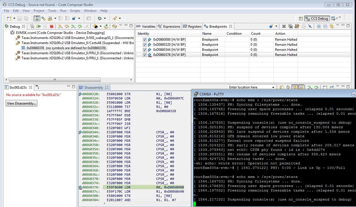
    Also, you should not place a breakpoint at the WFI instruction, this causes the WFI to evaluate as a NOP which is why you see the kernel suspend failure in the console output because the suspend code takes its abort path in that situation. Ideally you should disconnect from JTAG before attempting to suspend and then reconnect afterwards, otherwise the debugger normally will prevent the A8 from entering it's low power state.

    In the DeepSleep0 you should not be able to connect to either the A8 or the CM3.

  • >>Also, you should not place a breakpoint at the WFI instruction
    Agreed for real operation. We were just using this as a stop-mode debug step to prove the code was running in the right sequence.
  • Hello,

    I was able to modify my suspend sequence so that the GPIO0 button wakes up the Cortex M3. I can connect to the M3 during the "generic_wake_handler" function call and step through the power up sequence for a8_wake_ds0_handler. With this, the clock on CLKOUT1 is re-enabled successfully.

    I am now having difficulty with the A8 resuming properly. I have programmed the resume function's address (this routine is loaded into OCMC0 memory) into the IPC Reg0 during the DS0 command. However, I do not see it being executed. To try and determine whether the function is actually executing or not, I set up a gpio pin to toggle when the resume function is executed. JTAG won't connect unfortunately. After waking up the CM3, I do not see the gpio pin toggle, so I do not believe the resume function is being executed.

    Should the address that is loaded into the ROM reset vector and IPC Reg0 be the physical or virtual address of the function in OCMC memory?

    Thank you.

  • Hello,

    That's good news. You must program the physical address into IPC reg 0. The MMU, if you are using it, must be reenabled after the jump into SRAM, in Linux it is reenabled after jumping back to DDR. All restore actions done from the OCMC code must be done using the physical addresses of anything you are accessing.

    Regards,

    Dave

  • I have verified that the physical address that I am programming into IPC0 REG0 during the DS0 command corresponds to my restore function in assembly. It is a bit more complicated though. This platform is a custom design based on the EVM platform and we are using WEC2013. By default WEC2013 uses THUMB2 instructions only. Because of this, when the build system generates the final bootloader and OS images, it pre-pends the blx ARM command to the images to switch the core from ARM to THUMB2 automatically. So as soon as Romcode jumps to our bootloader's first instruction the system is running with THUMB2.

    Because of this, the instructions that are copied into OCMC0 memory are all THUMB2. However, the restore function is compiled under THUMB2, and the address to this resume function is not 4-byte aligned due to the thumb instruction. I think this is why the A8 is not resuming properly. I am going to try and add the ARM2THUMB switch to the resume function and program and set the resume address to this ARM instruction instead.

  • Hey Dave, Shin,

    I ported all of my changes for DeepSleep0 to the WEC7 BSP for the EVM reference hardware. I did this because WEC7 compiles for ARM instructions unlike WEC2013. This way the resume address programmed in IPC_MSG_REG0 would be a valid instruction. Unfortunately, this does not appear to have been the problem. I now have the EVM hardware back to the same point of failure as I had our custom hardware at. The Cortex-M3 will wake up from DS0 and will call the wake up handler to turn on the MPU domain, but the A8 does not seem to jump to the resume address.

    Is there any way to confirm that the ROM code that is being executed at DS0 wakeup is actually jumping to our address in OCMC0 memory? Is there any way to verify that the contents of the memory is still valid when the Cortex-M3 wakes up?

    Thank you,

    Geoff

  • Do you have a JTAG debugger? You may be able to connect to the processor via JTAG and determine the state. You can try to connect to both A8 and M3 and see the status of each processor.
  • Yes, I have the XDS100V2 jtag. It is possible to connect to the CM3 after I press the GPIO0 button. I have a while() loop in the PM firmware on the CM3 in the a8_wake_ds0_handler() function. So after I press the button and connect with the JTAG i see it in this while loop. I can step through this code and I can verify that it is calling to wake the MPU power domain. At this point the A8 should be executing ROM code and jumping to our IPC_MSG_REG0 resume address, but it is not possible to connect to it with the jtag so I cannot verify if this is happening.

  • Geoff,

    I realize this is an old thread but since your question is unanswered and I have just solved that mystery myself:

    The reason for the CM3 not getting the IRQ2 from PRCM is that the MPU clockdomain doesn't idle while ICEPick doesn't release the clock request. In the standard enable sequence for the A8 TAP, the value 0x2008 is written to the TAPs core register (0x60) for the A8. This keeps the clock request asserted at all times.

    If you manage to write 0x2000 into that register while the A8 is waiting in WFI, you will see that the CM3 immediately receives the interrupt and completes the sleep sequence (shuts down MPU clock domain, powers down PLLs etc). I cannot say how to achieve that with CCS, I'm using OpenOCD and there the command would be "icepick_c_router <icepick-tap-name> 1 6 0 0x2000"

    However, the debugger will of course now loose contact with the target because the necessary clocks are off and there are more problems in resume (some internal logic will keep the A8 halted in warm reset) which I have not yet been able to overcome myself.