This thread has been locked.

If you have a related question, please click the "Ask a related question" button in the top right corner. The newly created question will be automatically linked to this question.

AM3351: Bootloader fails to load from MMC0

Part Number: AM3351

I'm using an AM3351 processor and booting from micro SD card, with TI SDK 3.00. In some cases on startup (perhaps 1 out of 10 tries), the processor fails to detect the bootloader on my SD card (MMC0) and returns the UART output CCCCCCCC. This problem can quickly be circumvented with another power cycle, but this solution will be problematic for our eventual application.

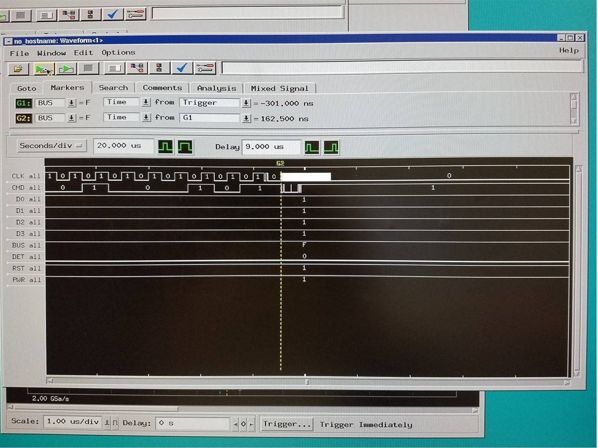
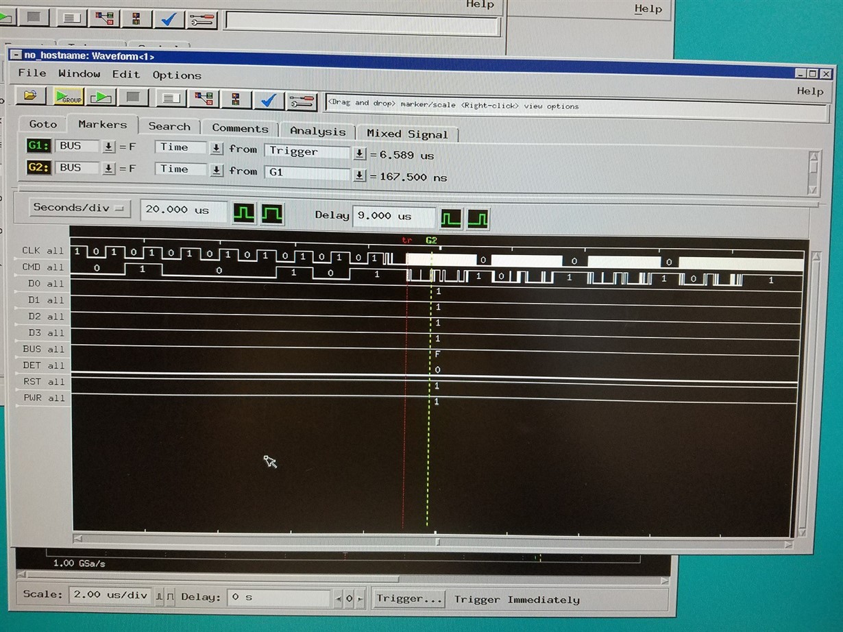
Looking at the MMC0 CMD signal and CLK lines on a scope, it appears to fail when transitioning from low speed to high speed data communication. In both good and bad startup cases, I see command CMD4 or SET_DSR followed by the bytes 04, 04, 00, 00. This is the last command before transitioning to high speed. Once high speed communication begins, in the cases where it fails to start the CMD line goes high and remains high.

Has anyone experienced a similar problem trying to run the bootloader from an SD card? I know that in many cases the MLO and u-boot.img files are stored in on-board memory. Please let me know if you have any suggestions.

Best regards,

Chris

  • This is unusual. It may be due either to board related issues or SD card problem. Have you tried with different SD cards? Is this a single board or do you see the same issue on multiple boards? Can you post the MMC0 portion of your schematic?
  • Good morning Biser,

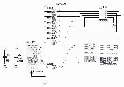
    Thank you for your quick response and help on the project. We've been working around this problem for the past ~5 months and in the process have tried many different SD card manufacturers, e.g. Lexar, and multiple boards. I've copied the micro SD card portion of the schematic below for reference. Have there been any similar problems using u-boot bootloaders on MMC0? Any suggestions after reviewing the schematic?

    Best regards,

    Chris

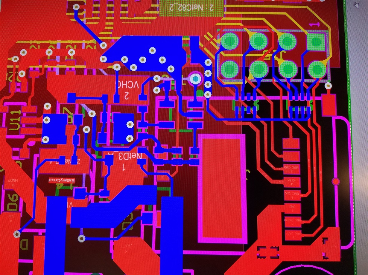
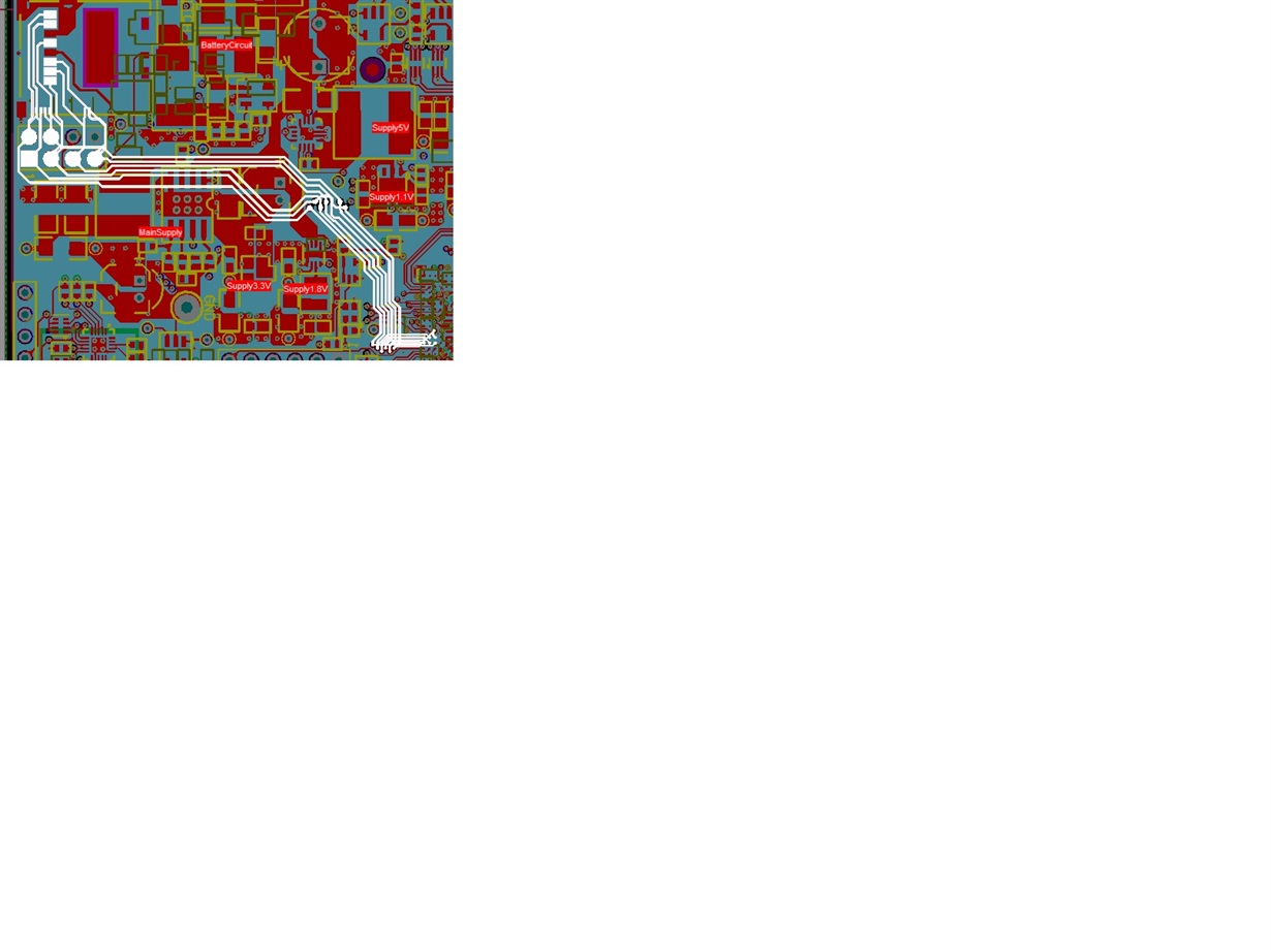
  • This seems OK, except for the pullup on the MMC_CLK line, which is not necessary. What worries me is this 2x4 header. How is it placed on the layout? If there are stubs from the MMC signal traces to it, this may cause problems. Also, do you have a serial resistor on the MMC_CLK line, placed close to the processor?
  • The pullups are to provide stability during initial conditions before the peripheral has been set up. The artwork looks like:

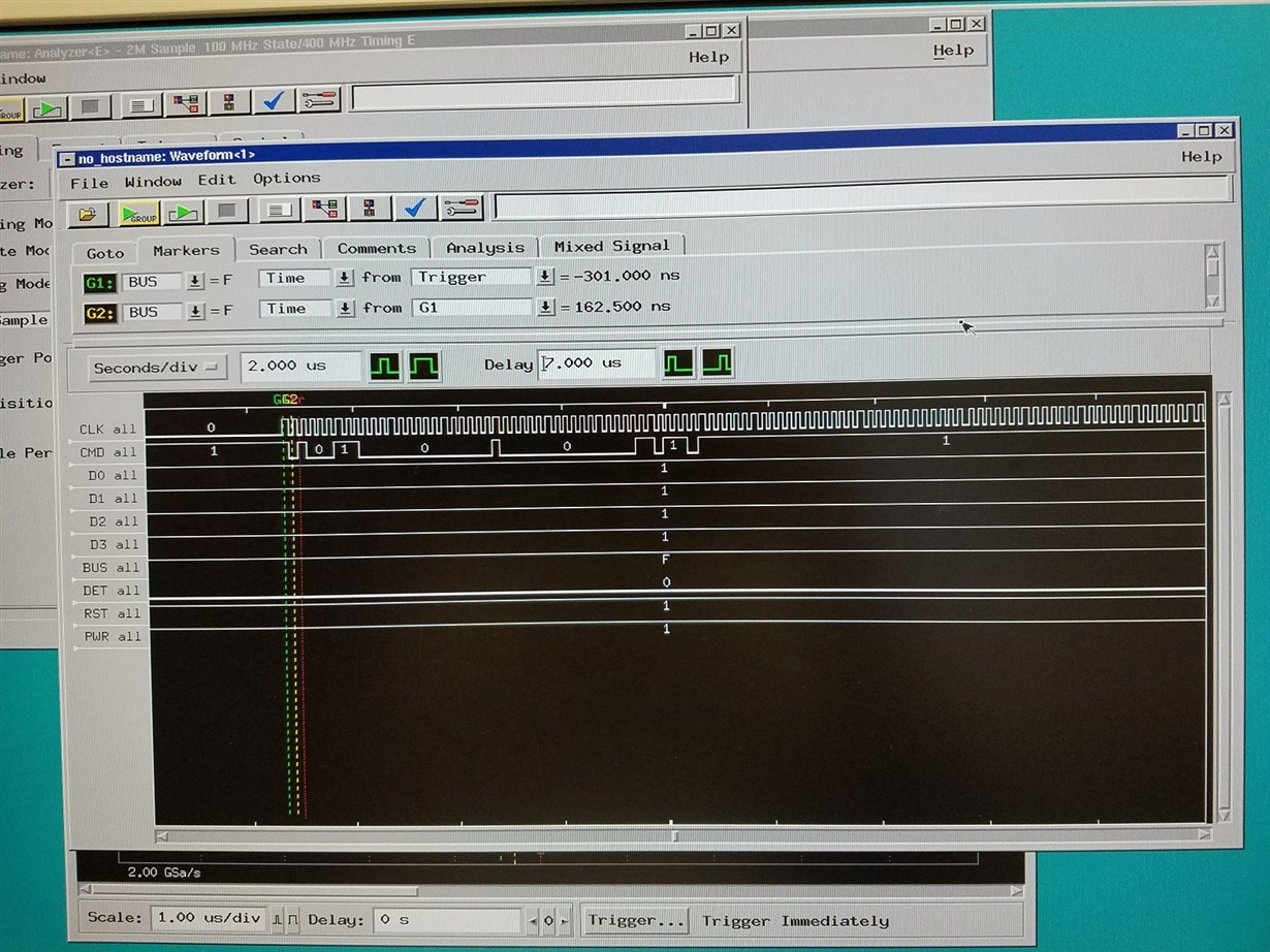
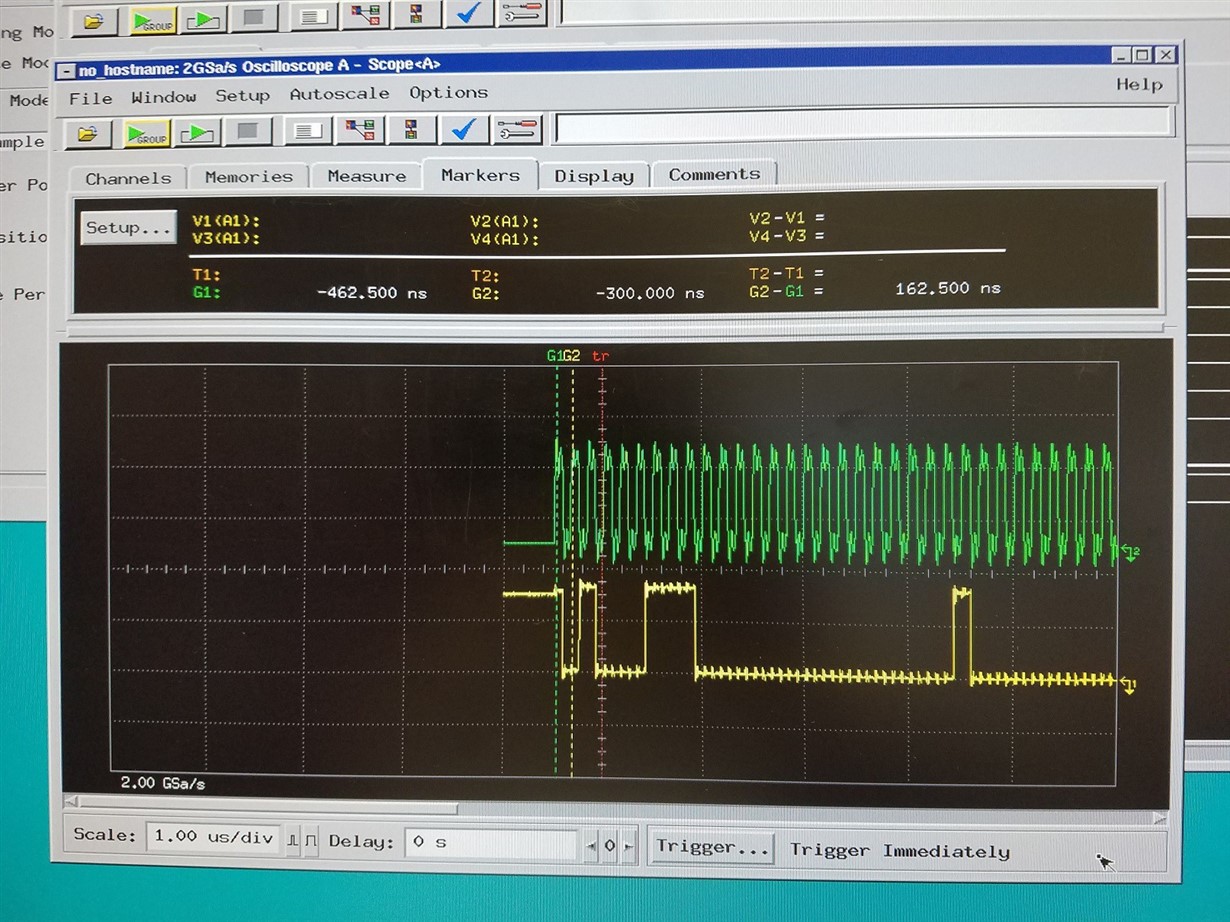
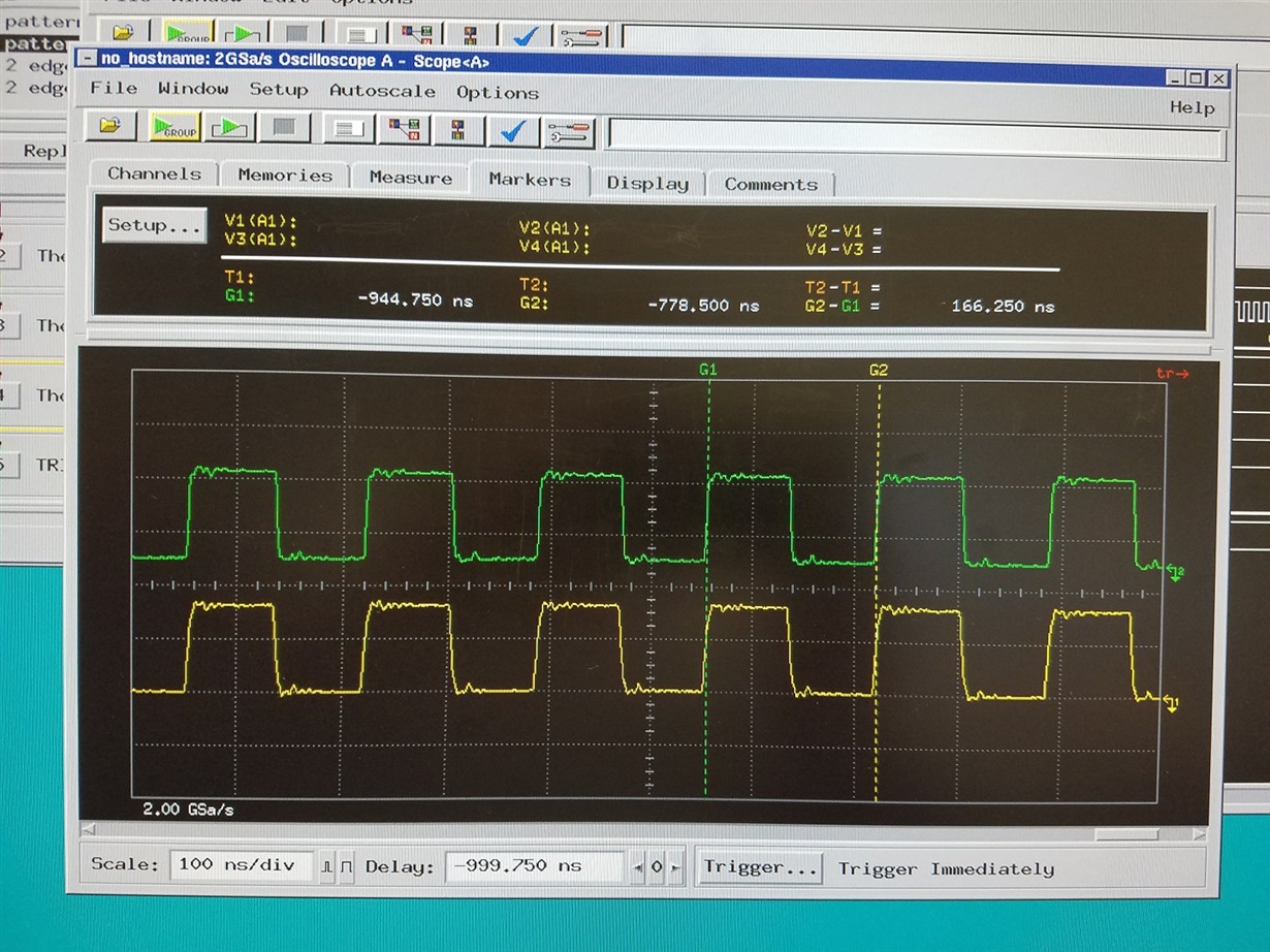
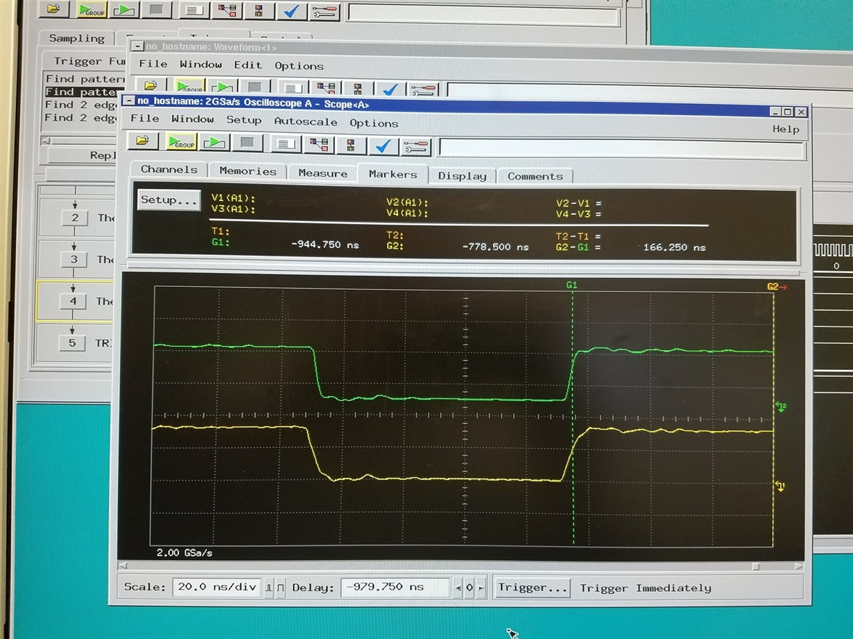
  • The issue seems to be during the initialization by the Sitara. At one point in the initialization sequence, the clock changes from around 68Khz to around 6Mhz. When that happens, either the data continues on the CMD line (successful boot) or it terminates (failed boot). The signals are captured with a logic analyzer and a scope. The signals themselves look OK. See pics of failed initialization:

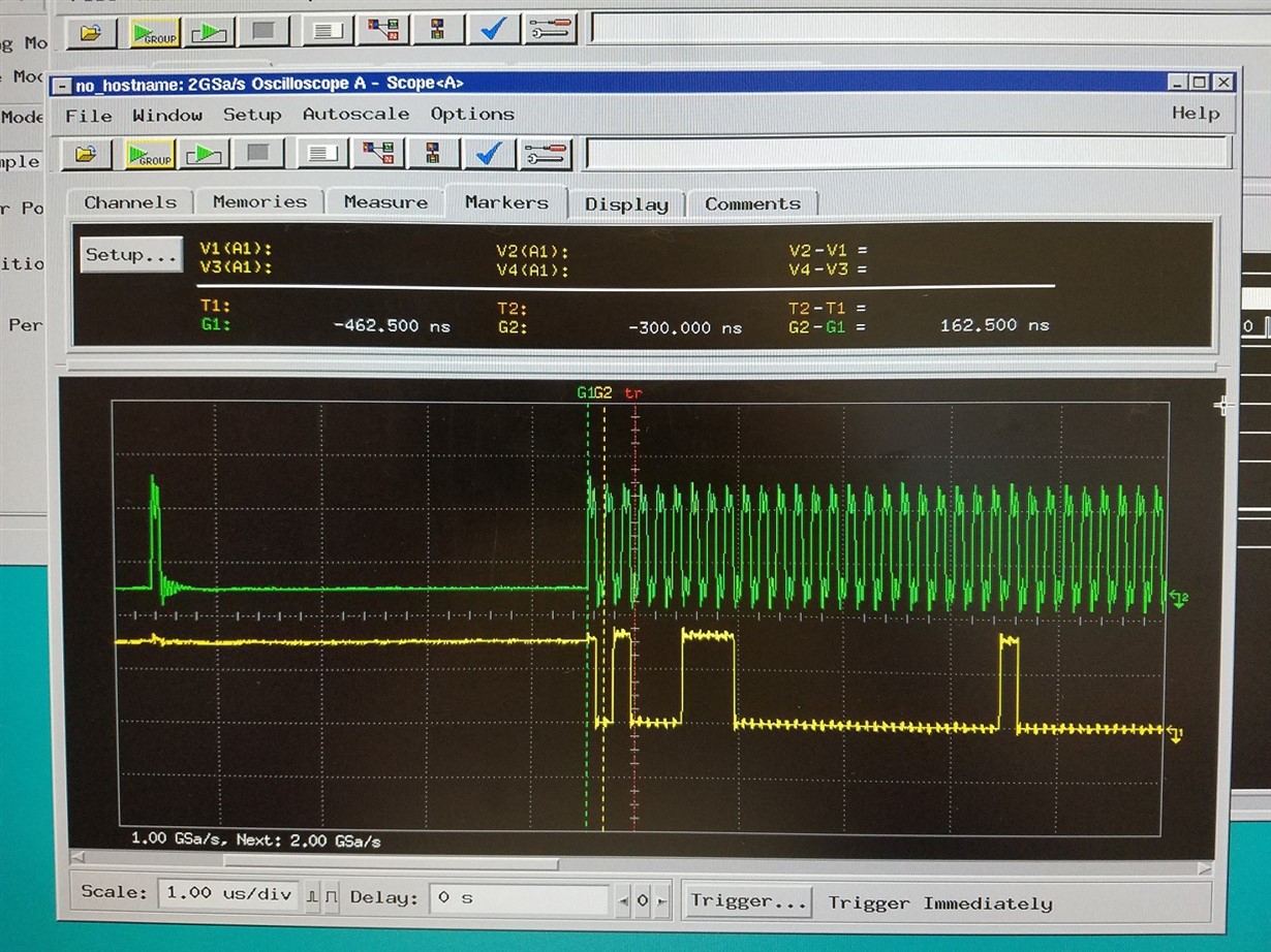
    A successful initialization looks like:

  • How long are the MMC traces, especially CLK and CMD? Where do you capture the scope shots? It should be at the processor side to see if there are any reflections. Have you tried placing a 22Ohm serial resistor on the CLK line, close to the processor?
  • The signals are captured at the 2x4 header. All of the signals are just over 3" long, see artwork. I would suspect that if there were any clocking issues, crosstalk issues, or other artwork related problems the interface would be continuously flaky and not work reliably even if it did initialize successfully. Once it is initialized, and running full speed, it works fine. The problem with this failure is that once it fails, the only way to recover is to power cycle or reset. I have been using the boot sequence where SYSBOOT[4:0] is 10111b. This attempts to boot from the MMC0 interface first, then SPI0, then UART0, then USB0. I monitor the UART interface for debugging and I know that if I see the 'C's coming out of the UART port, it fails. The boot is over and done. I began to experiment with the boot sequence and found that if I select SYSBOOT[4:0] to be 11010b it doesn't fail to boot. That boot sequence starts with the XIP interface, which is not supported in our system. I verified that the initialization of that interface by the internal boot code wouldn't cause problems in the system and I expect it to fail and try the next peripheral in the list which is UART0. Since the system doesn't boot from there, it fails as well and the next peripheral is selected which is SPI0. Again there is no way to boot from SPI0,so it fails and MMC0 is selected. It boots successfully from MMC0 over 90% of the time now. I do, however, see an occasional failure of the MMC interface in this sequence. When that happens, the boot sequence starts over, the other peripherals fail again, and the next MMC0 boot is successful. I didn't see the sequence retry with the other boot sequence. I suspect that since our USB0 interface, the last peripheral in that sequence, is connected to a HUB chip that has devices connected to it, that the USB boot interface hangs under these conditions so it doesn't retry the boot sequence under those conditions. While it looks like this solution may solve the boot reliability issue, it doesn't explain why there were so many problems, or any problems for that matter, with the other sequence. I'm wondering if there is an initialization time requirement for the SD card internally and it's being violated sometimes. As shown in my previous post, I have found where the MMC boot fails, I just don't know why yet.

  • James, let's go back to the question that Biser raised: Do you have a series resistor on the MMC_CLK signal?
    I see a slight stair step in the clock signal from the scope shots you provided. This can cause the issue you are seeing, because the MMC clock output is also looped back at the IO and used as a clock input while reading the data. If that slight hitch in the clock signal is close to the voltage threshold, it can be interpreted as an extra clock edge, causing error in the data that is read. Since the scope shots are at the header, it is not representative of what the processor sees, but it is indicating there are reflections on the signal.
    Because the hitch on the clock signal is caused by reflections on the trace, we recommend putting a series resistor close to the processor to move the reflection away from the voltage threshold of the clock signal.

    Regards,
    James
  • We inserted a 22 ohm resistor in series with the MMC clock at the processor. The signal from the processor pin to the resistor was approximately 3mm. I set the SYSBOOT[4:0] to our original 10111b, which means it will try the MMC device first. I booted the circuit 100 times. There were 25 failed boot sequences where the processor hung. There were two new failures where the boot hung part way through the boot sequence. I hadn't seen that before. In fact, that is what I would expect to happen if there was a problem with the clock or cross talk or some other physical issue. Up to this time, I haven't seen any of those types of issues. Then the resistor was removed. The scope shots here show the clock signal at each end of the trace taken just after the clock switches from around 60Khz to about 6Mhz. The yellow trace is at the processor where the resistor was and the green trace is at the header block at he MMC card. The scope is an Agilent 16534A 1G bandwidth scope with 500Mhz bandwidth probes.