This thread has been locked.

If you have a related question, please click the "Ask a related question" button in the top right corner. The newly created question will be automatically linked to this question.

RTOS/AM5726: EDMA constant addressing mode

Part Number: AM5726

Tool/software: TI-RTOS

Dear all!

I need to permanently translate some peripheria registers to some MPU0 memory address. How it do correctly?

I try to use EDMA::QDMA channel. According processor technical reference manual, EDMA channels has "constant addressing mode". This mode work if Source or Destination is FIFO and its address is align by 256 bit.

So, i configure params of QDMA channel:

  • OPT with flags: STATIC, FWID_32BIT (one register, for first time), DAM
  • DST
  • SRC
  • ACNT=4
  • BCNT=1
  • CCNT=1
  • SRCBIDX=0
  • DSTBIDX=0
  • SRCCIDX=0
  • DSTCIDX=0
  • LINK=0xffff
  • BCNTRLD=0

And it not work. If i use INCRIMENT mode, transaction is proccessed seccessful, but only first time.
Ofcourse, i can use interrupt handler for reenable transaction, but it wrong way.

Why the "constant addressing mode" is not work?
What is true way for this purpose?

Thankyou

  • The RTOS team have been notified. They will respond here.
  • Hi,

    Do you have details what is the source address and destination address? You set DAM bit, are you writing into a peripheral registers by EDMA? If you are trying to read from peripherals using MPU, I thought SAM bit should set, not the DAM bit?

    As the constant addressing mode failed to transfer data, do you see any error in ERRSTAT register?

    Regards, Eric
  • Hi, Eric.

    My main goal is found the way to do PCIe EP doorball (interrupt from Host to Device) registers.

    One of variant is use GIC::SGI and translate GICD_SPENDSGIRn (MPU address: 0x48211f20) via EDMA into PCIe::BAR inbound memory.

    GIC::SGI is work well (e2e.ti.com/.../2514450): if i write into the address from MPU the interrupt handler is raising.

    But not working if i use EDMA "link to self transfer" mode or "constant FIFO" mode.

    For debugging, i firstly trying to map address 0x40500000 and 0x40520000 (OCMC_RAM_3).

    In "link to self transfer" mode, data from source address wrote to destination, but only once.

    In "constant FIFO" mode no one valid transaction is happends.

    How can i config EDMA and what mode is use to make it permanently translate address if write event is happends (without MPU participation)?

    May be you know batter way to achieve the main goal?

    Thankyou.

  • Hi,

    Seems there are some issues when you want to use EDMA to write the MPU_INTC GICD_SPENDSGIR register. "My main goal is found the way to do PCIe EP doorball (interrupt from Host to Device) registers."

    Can you explain a system diagram? Which device is PCIE RC, which is EP? What is the PCIE data flow? You want send an interrupt from RC to EP? On EP side what you want to do with the interrupt?

    Regards, Eric
  • Hi, Eric

    Please, look at diagram below

    Using AM57x processor, i want to do PCIe device: EP mode on device and RC mode on PC.

    Via BAR, i can share some memory regions for data exchange purporse from PC to device and back. After that, i need to tell PC driver / Device about data renew fact.

    To inform PC driver, i can use MSI / Legacy interrupt. Its ok. But to another direction i can't found any mechanism, except use registers polling for changes detected.

    So. i looking for different methods to do "backward interrupts"

    One of them, is use GIC SGI and map few registers on BAR addresses. If it will work, then if PC driver will write at it's addresses, then SGI Handlers is raising.

    The problem is how to correctly access to some GIC registers from PCIe side.

    Under this theme, i try to use EDMA for data translation (from BAR mermoy region to registers address). If i understood correctly, in EDMA has event mode and it cat do transaction on fact data changes (in my case, BAR memory regioin data changes)

    Thankyou

  • Hi,

    Thanks for explaining your usage case! In ourPCIE example, there is one inbound translation region setup, it converts an incoming address into global address inside the chip:

    ibCfg.ibStartAddrLo = PCIE_IB_LO_ADDR_RC;
    ibCfg.ibStartAddrHi = PCIE_IB_HI_ADDR_RC;
    ibCfg.ibOffsetAddr = (uint32_t)pcieConvert_CoreLocal2GlobalAddr ((uint32_t)dstBuf.buf);

    So, in your case, can you add an additional inbound translation. For an incoming address A, you convert it to the GIC register region? So, your PCIE RC (host PC) writes to this address A, it lands on the GIC register on the EP side.

    Regards, Eric
  • Hi, Eric

    In the next couple of days I have a vacation.

    I'll check it as soon as I get back.
    Be sure to report the results.

    Thank you for the help.

  • Hi,

    Do you have any update for this?

    Regards, Eric
  • Hi, Eric

    Sorry for the long wait. I just came back from vacation.

    No, it's not work for me.

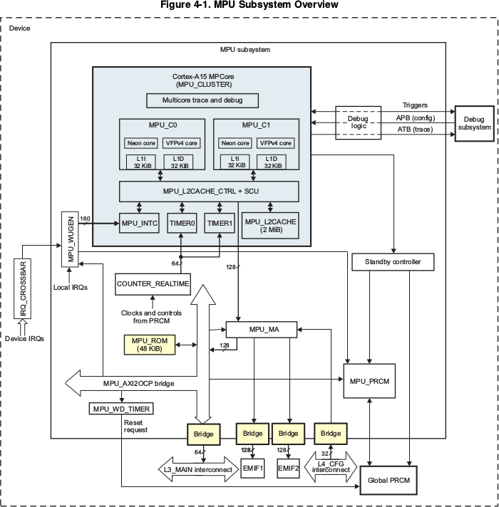
    I'm not so sure anymore that this should work . According the Sitara TRM, MPU_INTC is connected to A15 L2 Cache:


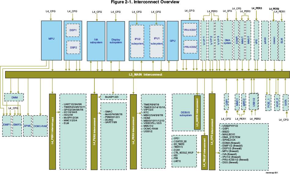
    if i understood correctly, no one DMA, MMU2 (PCIe) or any pereferia can work directly with A15 L2 cache:

    Am i right?


    Thankyou.


  • Hello, Eric!

    Do you have any update for this?

    Thankyou

  • Hi,

    What I think is differently: For example, there are 8 GPIO instances, I assume you don't use all of them. We have GPIO driver example on AM57x EVM. The driver configured GPIO interrupt to toggle the LED. How the interrupt was triggered? You can look at the main_led_blink.c:

    /* Trigger interrupt */
    GPIOTriggerPinInt(gpioBaseAddr, 0, gpioPin);

    This function is inside CSL:

    void GPIOTriggerPinInt(uint32_t baseAdd,
    uint32_t intLine,
    uint32_t pinNumber)
    {
    if (GPIO_INT_LINE_1 == intLine)
    {
    HW_WR_REG32(baseAdd + GPIO_IRQSTATUS_RAW_0, (uint32_t) 1 << pinNumber);
    }
    else
    {
    HW_WR_REG32(baseAdd + GPIO_IRQSTATUS_RAW_1, (uint32_t) 1 << pinNumber);
    }
    }

    That is, by writing to GPIO_IRQSTATUS_RAW register you can trigger a GPIO interrupt locally.

    For you, you have a PCIE RC-----PCIE EP, on the EP side, you can define an inbound translation to a GPIO register region. For illustration, let say you used GPIO1 0x4AE1 0000.

    Then on the PCIE RC side, you can do a map like address 0x2010_0000 to outbound address 0x9000_0000. Then at the EP side, address 0x9000_0000 map to 0x4ae1_0000. Then you should be able to read/write GPIO of EP from RC side, including to trigger an interrupt.

    Regards, Eric
  • Thankyou, for help!

    Good luck!