Hi there,
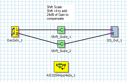
We are testing a 192kHz sample rate through the miniDSP. We trying to configure the use of FIlter B which will introduce a -24dB gain error which will supposedly be fixed by a +4 shift (more info further). The AIC3254 is on a product in which I have i2c communication (via) DSP Driver and a McASP interface between the AIC3254 and the DSP. We thus interpret pps driver files register settings and configure the codec without a EVM board via i2c.
Attempting to replicate something similar to this post
AS SOON AS I CONFIGURE THE USE OF THE miniDSP_A the ADC samples are all zero.
I have been trying to configure the miniDSP for a simple process flow as below:
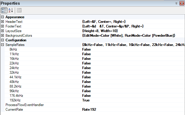
The Framework used is not the default 192kHz framwork as I would like to use Filter B for the bandwidth, the framwork used I assume uses filter B.
The process flow is setup as below:
With the SystemSettings code edited as follows:
(I am commenting out all the DAC settings as for now I only want to get the ADC running through the miniDSP, Is this fine?)
(I have also commented out any initialization, power up, routing and clock setup as this is done in the miniDSP driver, I will provide details further)
;-----------------------------------------------------------------------------------
; Software Reset
;-----------------------------------------------------------------------------------
	;reg[  0][  1] = 0x01	; Initialize the device through software reset
    ;reg[254][  0] = 0x0a	; Delay 10ms

;-----------------------------------------------------------------------------------
; Configure Power Supplies
;-----------------------------------------------------------------------------------
	%%if (%%prop(TargetBoard) == 2)
; AIC3254EVM-U specific configuration

	;reg[  1][  2] = 0xa9	; Power up AVDD LDO
	;reg[  1][  1] = 0x08	; Disable weak AVDD to DVDD connection
	;reg[  1][  2] = 0xa1	; Enable Master Analog Power Control, AVDD LDO Powered

	%%else
; AIC3254EVM-K specific configuration
	;reg[  1][  1] = 0x08	; Disable weak AVDD to DVDD connection
	;reg[  1][  2] = 0x00	; Enable Master Analog Power Control

	%%endif

	;reg[  1][ 71] = 0x32	; Set the input power-up time to 3.1ms
	;reg[  1][123] = 0x01	; Set REF charging time to 40ms (automatic)
;	;reg[254][  0] = 0x28	; Delay 40ms for REF to Power Up

;-----------------------------------------------------------------------------------
; Load miniDSP Code
;-----------------------------------------------------------------------------------
	PROGRAM_ADC		; miniDSP_A coefficients and instructions
	;PROGRAM_DAC		; miniDSP_D coefficients and instructions

;-----------------------------------------------------------------------------------
; Signal Processing Settings
;-----------------------------------------------------------------------------------
	;reg[  0][ 60] = 0x00	; Use miniDSP_D for signal processing
	reg[  0][ 61] = 0x00	; Use miniDSP_A for signal processing

	%%if ("%%prop(FrameworkType)" == "AIC3254App8x4x")
	reg[  0][ 17] = 0x08	; 8x Interpolation
	reg[  0][ 23] = 0x04	; 4x Decimation
	%%endif

	%%if ("%%prop(FrameworkType)" == "AIC3254App4x2x")
	reg[  0][ 17] = 0x04	; 4x Interpolation
	reg[  0][ 23] = 0x02	; 2x Decimation
	%%endif

	%%if ("%%prop(FrameworkType)" == "AIC3254App2x1x")
	reg[  0][ 17] = 0x02	; 2x Interpolation
	reg[  0][ 23] = 0x01	; 1x Decimation
	%%endif

	;IDAC  = %%prop(miniDSP_D_Cycles)
	IADC  = %%prop(miniDSP_A_Cycles)

	%%if (%%prop(miniDSP_A_Adaptive) == 1)
	;reg[  8][  1] = 0x04	; adaptive mode for ADC
	%%endif

	%%if (%%prop(miniDSP_D_Adaptive) == 1)
	;reg[ 44][  1] = 0x04	; adaptive mode for DAC
	%%endif

;-----------------------------------------------------------------------------------
; Clock and Interface Configuration
;-----------------------------------------------------------------------------------
; USB Audio supports 8kHz to 48kHz sample rates
; An external audio interface is required for 88.2kHz to 192kHz sample rates
;-----------------------------------------------------------------------------------
	%%if (%%prop(SampleRate) == 176400 || %%prop(SampleRate) == 192000)
	;reg[  0][  5] = 0x91	; P=1, R=1, J=8
	;reg[  0][  6] = 0x08	; P=1, R=1, J=8
	;reg[  0][  7] = 0x00	; D=0000 (MSB)
	;reg[  0][  8] = 0x00	; D=0000 (LSB)
	;reg[  0][  4] = 0x03	; PLL_clkin = MCLK, codec_clkin = PLL_CLK, PLL on
	;reg[  0][ 12] = 0x88	; MDAC = 8, divider powered on
	;reg[  0][ 13] = 0x00	; DOSR = 32 (MSB)
	;reg[  0][ 14] = 0x20	; DOSR = 32 (LSB)
	reg[  0][ 18] = 0x02	; NADC = 2, divider powered off
	reg[  0][ 19] = 0x88	; MADC = 8, divider powered on
	reg[  0][ 20] = 0x20	; AOSR = 32
	reg[  0][ 11] = 0x82	; NDAC = 2, divider powered on

	%%endif

	%%if (%%prop(SampleRate) == 88200 || %%prop(SampleRate) == 96000)
	reg[  0][  5] = 0x91	; P=1, R=1, J=8
	reg[  0][  6] = 0x08	; P=1, R=1, J=8
	reg[  0][  7] = 0x00	; D=0000 (MSB)
	reg[  0][  8] = 0x00	; D=0000 (LSB)
	reg[  0][  4] = 0x03	; PLL_clkin = MCLK, codec_clkin = PLL_CLK, PLL on
	reg[  0][ 12] = 0x88	; MDAC = 8, divider powered on
	reg[  0][ 13] = 0x00	; DOSR = 64 (MSB)
	reg[  0][ 14] = 0x40	; DOSR = 64 (LSB)
	reg[  0][ 18] = 0x02	; NADC = 2, divider powered off
	reg[  0][ 19] = 0x88	; MADC = 8, divider powered on
	reg[  0][ 20] = 0x40	; AOSR = 64
	reg[  0][ 11] = 0x82	; NDAC = 2, divider powered on
	%%endif

	%%if (%%prop(SampleRate) == 44100 || %%prop(SampleRate) == 48000)
	reg[  0][  5] = 0x91	; P=1, R=1, J=8
	reg[  0][  6] = 0x08	; P=1, R=1, J=8
	reg[  0][  7] = 0x00	; D=0000 (MSB)
	reg[  0][  8] = 0x00	; D=0000 (LSB)
	reg[  0][  4] = 0x03	; PLL_clkin = MCLK, codec_clkin = PLL_CLK, PLL on
	reg[  0][ 12] = 0x88	; MDAC = 8, divider powered on
	reg[  0][ 13] = 0x00	; DOSR = 128 (MSB)
	reg[  0][ 14] = 0x80	; DOSR = 128 (LSB)
	reg[  0][ 18] = 0x02	; NADC = 2, divider powered off
	reg[  0][ 19] = 0x88	; MADC = 8, divider powered on
	reg[  0][ 20] = 0x80	; AOSR = 128
	reg[  0][ 11] = 0x82	; NDAC = 2, divider powered on
	%%endif

	%%if (%%prop(SampleRate) == 32000)
	reg[  0][  5] = 0x91	; P=1, R=1, J=8
	reg[  0][  6] = 0x08	; P=1, R=1, J=8
	reg[  0][  7] = 0x00	; D=0000 (MSB)
	reg[  0][  8] = 0x00	; D=0000 (LSB)
	reg[  0][  4] = 0x03	; PLL_clkin = MCLK, codec_clkin = PLL_CLK, PLL on
	reg[  0][ 12] = 0x88	; MDAC = 8, divider powered on
	reg[  0][ 13] = 0x00	; DOSR = 192 (MSB)
	reg[  0][ 14] = 0xc0	; DOSR = 192 (LSB)
	reg[  0][ 18] = 0x02	; NADC = 2, divider powered off
	reg[  0][ 19] = 0x8c	; MADC = 12, divider powered on
	reg[  0][ 20] = 0x80	; AOSR = 128
	reg[  0][ 11] = 0x82	; NDAC = 2, divider powered on
	%%endif

	%%if (%%prop(SampleRate) == 22050 || %%prop(SampleRate) == 24000)
	reg[  0][  5] = 0x91	; P=1, R=1, J=8
	reg[  0][  6] = 0x08	; P=1, R=1, J=8
	reg[  0][  7] = 0x00	; D=0000 (MSB)
	reg[  0][  8] = 0x00	; D=0000 (LSB)
	reg[  0][  4] = 0x03	; PLL_clkin = MCLK, codec_clkin = PLL_CLK, PLL on
	reg[  0][ 12] = 0x88	; MDAC = 8, divider powered on
	reg[  0][ 13] = 0x01	; DOSR = 256 (MSB)
	reg[  0][ 14] = 0x00	; DOSR = 256 (LSB)
	reg[  0][ 18] = 0x02	; NADC = 2, divider powered off
	reg[  0][ 19] = 0x90	; MADC = 16, divider powered on
	reg[  0][ 20] = 0x80	; AOSR = 128
	reg[  0][ 11] = 0x82	; NDAC = 2, divider powered on
	%%endif

	%%if (%%prop(SampleRate) == 16000)
	reg[  0][  5] = 0x91	; P=1, R=1, J=24
	reg[  0][  6] = 0x18	; P=1, R=1, J=24
	reg[  0][  7] = 0x00	; D=0000 (MSB)
	reg[  0][  8] = 0x00	; D=0000 (LSB)
	reg[  0][  4] = 0x03	; PLL_clkin = MCLK, codec_clkin = PLL_CLK, PLL on
	reg[  0][ 12] = 0x88	; MDAC = 8, divider powered on
	reg[  0][ 13] = 0x01	; DOSR = 384 (MSB)
	reg[  0][ 14] = 0x80	; DOSR = 384 (LSB)
	reg[  0][ 18] = 0x02	; NADC = 2, divider powered off
	reg[  0][ 19] = 0x98	; MADC = 24, divider powered on
	reg[  0][ 20] = 0x80	; AOSR = 128
	reg[  0][ 11] = 0x82	; NDAC = 2, divider powered on
	%%endif

	%%if (%%prop(SampleRate) == 11025)
	reg[  0][  5] = 0x91	; P=1, R=1, J=16
	reg[  0][  6] = 0x10	; P=1, R=1, J=16
	reg[  0][  7] = 0x00	; D=0000 (MSB)
	reg[  0][  8] = 0x00	; D=0000 (LSB)
	reg[  0][  4] = 0x03	; PLL_clkin = MCLK, codec_clkin = PLL_CLK, PLL on
	reg[  0][ 12] = 0x88	; MDAC = 8, divider powered on
	reg[  0][ 13] = 0x02	; DOSR = 512 (MSB)
	reg[  0][ 14] = 0x00	; DOSR = 512 (LSB)
	reg[  0][ 18] = 0x02	; NADC = 2, divider powered off
	reg[  0][ 19] = 0xa0	; MADC = 32, divider powered on
	reg[  0][ 20] = 0x80	; AOSR = 128
	reg[  0][ 11] = 0x82	; NDAC = 2, divider powered on
	%%endif

	%%if (%%prop(SampleRate) == 8000)
	reg[  0][  5] = 0x91	; P=1, R=1, J=24
	reg[  0][  6] = 0x18	; P=1, R=1, J=24
	reg[  0][  7] = 0x00	; D=0000 (MSB)
	reg[  0][  8] = 0x00	; D=0000 (LSB)
	reg[  0][  4] = 0x03	; PLL_clkin = MCLK, codec_clkin = PLL_CLK, PLL on
	reg[  0][ 12] = 0x88	; MDAC = 8, divider powered on
	reg[  0][ 13] = 0x03	; DOSR = 768 (MSB)
	reg[  0][ 14] = 0x00	; DOSR = 768 (LSB)
	reg[  0][ 18] = 0x02	; NADC = 2, divider powered off
	reg[  0][ 19] = 0xb0	; MADC = 48, divider powered on
	reg[  0][ 20] = 0x80	; AOSR = 128
	reg[  0][ 11] = 0x82	; NDAC = 2, divider powered on
	%%endif


;-----------------------------------------------------------------------------------
; ADC Channel Configuration
;-----------------------------------------------------------------------------------
	;reg[  1][ 51] = 0x40	; Mic Bias enabled, Source = Avdd, 1.25V

	%%if (%%prop(TargetBoard) == 2)
; AIC3254EVM-U specific configuration
	;reg[  1][ 52] = 0x10	; Route IN2L to LEFT_P with 10K input impedance
	;reg[  1][ 54] = 0x40	; Route CM1L to LEFT_M with 10K input impedance
	;reg[  1][ 55] = 0x10	; Route IN2R to RIGHT_P with 10K input impedance

	%%else
; AIC3254EVM-K specific configuration
	;reg[  1][ 52] = 0x40	; Route IN1L to LEFT_P with 10K input impedance
	;reg[  1][ 54] = 0x40	; Route CM1L to LEFT_M with 10K input impedance
	;reg[  1][ 55] = 0x40	; Route IN1R to RIGHT_P with 10K input impedance

	%%endif

	;reg[  1][ 57] = 0x40	; Route CM1R to RIGHT_M with 10K input impedance
	;reg[  1][ 59] = 0x00	; Enable MicPGA_L Gain Control, 0dB
	;reg[  1][ 60] = 0x00	; Enable MicPGA_R Gain Control, 0dB
	;reg[  0][ 81] = 0xc0	; Power up LADC/RADC
	;reg[  0][ 82] = 0x00	; Unmute LADC/RADC

;-----------------------------------------------------------------------------------
; DAC Channel Configuration
;-----------------------------------------------------------------------------------
	;reg[  1][ 20] = 0x25	; De-pop: 5 time constants, 6k resistance
	;reg[  1][ 12] = 0x08	; Route LDAC to HPL
	;reg[  1][ 13] = 0x08	; Route RDAC to HPR
	;reg[  1][ 14] = 0x08	; Route LDAC to LOL
	;reg[  1][ 15] = 0x08	; Route LDAC to LOR
	;reg[  0][ 63] = 0xd4	; Power up LDAC/RDAC w/ soft stepping
	;reg[  1][ 16] = 0x00	; Unmute HPL driver, 0dB Gain
	;reg[  1][ 17] = 0x00	; Unmute HPR driver, 0dB Gain
	;reg[  1][ 18] = 0x00	; Unmute LOL driver, 0dB Gain
	;reg[  1][ 19] = 0x00	; Unmute LOR driver, 0dB Gain
	;reg[  1][  9] = 0x3c	; Power up HPL/HPR and LOL/LOR drivers
	;reg[  0][ 64] = 0x00	; Unmute LDAC/RDAC
As shown above the following are some highlighted configuration settings (are they correct)?
Clock Settings:
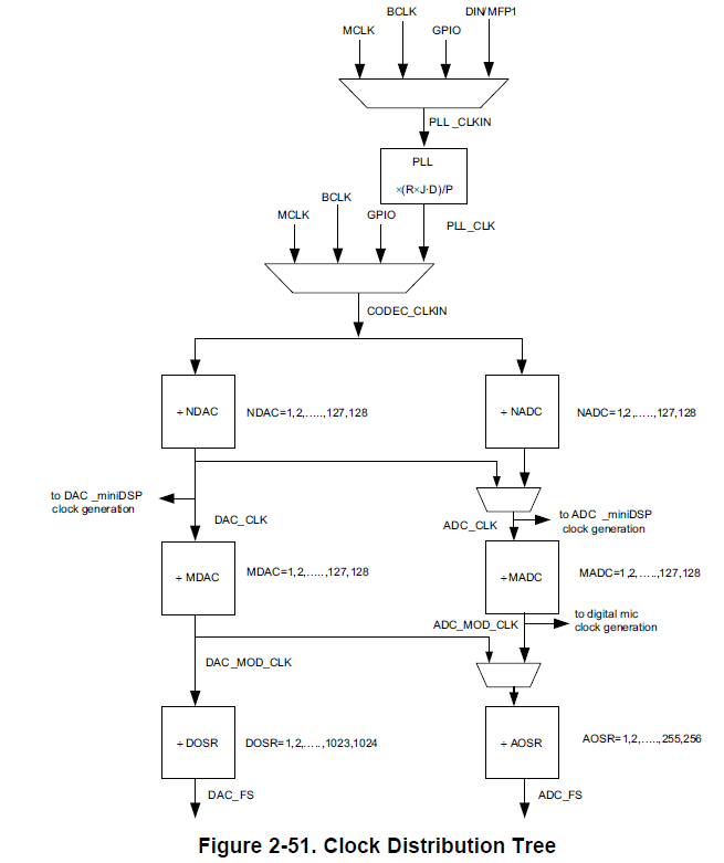
PLL is used = 98.304MHZ = CODEC_CLKIN
NADC = 2
MADC = 8
AOSR = 32
CODEC_CLKIN = NADC x MADC x ADC_FS = 2 x 4x 192000 = 98.304MHZ (Is this correct?)
I see in the clock distribution tree there is an indication that the mini DSP clock generation branches off after the NADC does this still mean my clock setup is correct, is it somewhat confusing to me?
Also in the reference post they use 2x decimation, Im not exactly sure why and where this 2x decimation comes from as I was under the impression the decimation is done with the hardware filters (Filter C) before the miniDSP based on the framework. How does it fit in with the clock rate settings and sample rate?
I have attached the process flow in case it is needed: